This article appeared in Make: Vol. 84. Subscribe for more great articles.

Years of 3D print and circuit hackery have led me to build some pretty crazy contraptions. I tend to favor the kinds of projects that combine art and function and require me to learn something new in order to complete. This project was inspired by the very cool fiber optic projects posted online by Martin Oehler (@maketvee on instructables), John-Paul Wenger (@ItsMrJP on X), and others. I am grateful to find the cool part of Twitter that celebrates people chasing their crazy ideas and sharing what they make.

Design Process


The design for this clock took a while. It evolved from several experimental versions, each one teaching me something new about the limitations and possibilities of combining the light pipes with a variety of different kinds of lights and materials. My goal from the start was to somehow turn these beautiful pipes into a digital clock, while still showing the pipes and how they change colors, to highlight the beauty of the light traveling to the digits.

Figure A


Figure A shows the original idea I sketched out on the back of an envelope, and Figure B is the first digital rendering done with 123D Design.

Figure B

As you can see, my first ideas relied heavily on suspending the pipes in place. The intent was to run them through a block of 3D-printed clear PETG that would be a bit blurry, but you could still see the pipes. This idea failed mostly because the block was too big to print on my machine.

Figure C


So, I made a more compact version next (Figure C). This one was smaller and more printable, but as I quickly found out, the pipes weren’t very visible, and there wasn’t enough contrast in order to be able to see the digits clearly.

Figure D


So, my next design focused more on contrast, and the possibility of encasing the pipes in acrylic for better visibility (Figure D ). I know. It looks like a potato. Moving on!


This is the point where I gave up on the idea for a while. I didn’t want to just make something that didn’t serve my original idea: a functional clock that highlighted the beauty of the light pipes. But I couldn’t let it go. After a week or so my brain was back on the case, working to solve the problem. How could I suspend the digits, see the lights, and keep it as simple as possible? At this point I was tired of experimenting with acrylic. Too messy!


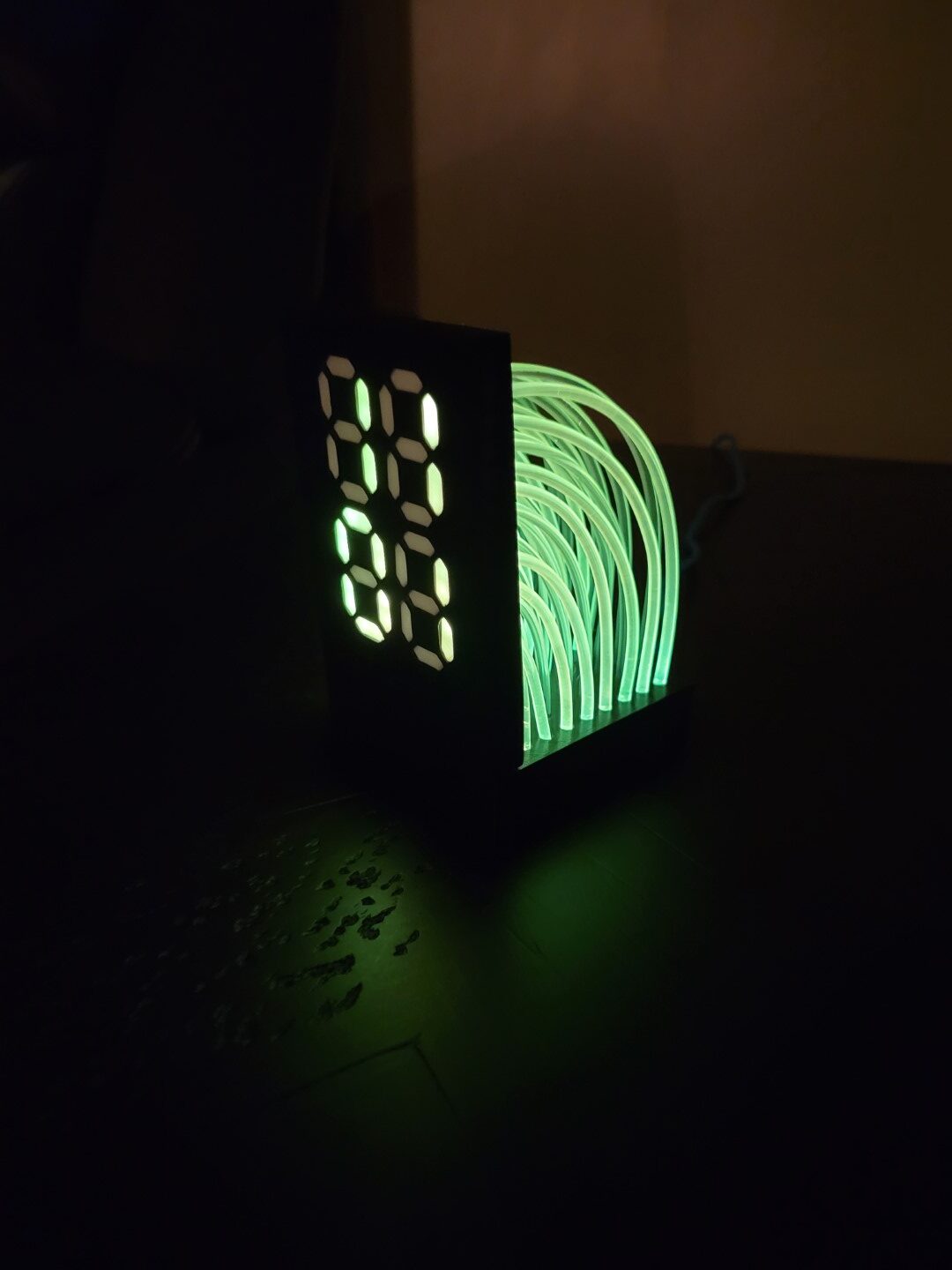
And so, the last version — the simplest of them all — was my favorite (Figure E ). I guess I had to go the long route, but at least I can say I learned a lot on the way.

Figure F


The cool part about this version is the holes for mounting the pipes. They’re cone shaped, and the narrowest part is slightly undersized for the PMMA to push through. This helps to grab the pipe and hold it so it’s less likely to fall back out. I found that super glue, hot glue, and even UV-cured acrylic resin failed to hold these pipes in place, so this friction-fit design saved the day. Figure F on the following page shows a close-up of the lens design.


The slight air gap between the end of the pipe and the face of the digit creates a smooth, diffused glow when lit.

Project Steps

3D Print The Parts

Figure F

Download the STL files from the repository, then print the following parts as is, no supports necessary (Figure F ). They already have correct orientation.

  • base.stl — print 1 in black
  • face.stl — print 1 in black
  • underside_lid.stl — print 1 in black, recommend using a brim
  • lens.stl — print 28 in white

Flash The Microcontroller

Download the clock code file, ClockSketch_v7-7SCv3-TFO-3.ino, from the repo. Using Arduino IDE, open the file and update the Wi-Fi SSID and password. Connect the ESP8266 board with the USB cable, then upload the code to the board.

This code is a slightly modified version of ClockSketch V7 by Daniel Cikic, aka Parallyze. It is is highly configurable, so play around with it if you like, but the version I have posted on GitHub is modified to work with this clock specifically.

Assemble The Circuit and Base

Figure H

Solder the circuit, following the schematic (Figure H ) and connecting wires to the underside of the MPU6050 and ESP8266 boards. The enclosure has a gap for the wires to pass through. If they’re wired on top, the LED matrix won’t have space.

Figure I

Secure the MPU6050 in the underside lid piece using the M2×6mm screw, and slide the ESP8266 into the slots (Figure I ). You can use glue to hold down the ESP8266 a bit more firmly, but once the clock is assembled, this part will not move.

Figure J

Make sure the LED matrix wires pass through the gap without lifting the matrix (Figure J ), so that it sits flat on the rails of the underside lid.
Now test the circuit by plugging it in. Also test the gyro by turning the piece upside down to change the color palette.

Figure K

Once the circuit is tested, slide the underside lid up into the clock base. Line up the oval opening with the micro-USB port of the ESP8266 (Figure K ), then push slightly up into the base. It shouldn’t need to be forced; if it’s hard to push, check the parts arrangement and make sure nothing is in the way. You should hear a few clicks when it goes in correctly.

If you need to pull the parts back out of the base, pinch slightly on the sides of the underside lid and pull down and back out.

Plug In The Pipes

Figure L

Slide the clock face piece into the base. The tab sticking out of the bottom should be inserted toward the light grid. When inserted correctly the face sits flush with the base, forming an L shape (Figure L ).

Figure M

Next, start cutting up the PMMA light pipes. I recommend cutting as you go. The lengths are not exact. I found that slightly longer than needed works best; if too short they won’t have tension on them and they’ll fall out. The spreadsheet image (Figure M) lists approximate lengths for each row and how they should be plugged in. I have highlighted a couple to get you started. For reference, the green 0 at the back corner of the grid lines up with the green zero at the top left of the first digit. The yellow 7 at the front of the grid, closest to the face, aligns with the bottom right of the last digit. And so on.

When you insert a light pipe into the back of a lens piece, don’t force it all the way. It should catch about halfway, and be slightly difficult to tug back out. Then snap the lens into the face.

Start at the bottom, with the row closest to the face, and work your way up/out. (Figures N – P).

Test and Enjoy!

The 7-segment numerals on the face should now be glowing with the correct time!

Conclusion

Glowing Recommendations

I may revisit this project to make improvements:
• There are 8 unused LEDs on the grid that are blacked out for now, but one day could be repurposed for other things such as showing AM/PM designations.
• It seems that a matte type of PLA holds the light pipes better than glossy PLA. I will be testing this theory more as I make theseGlowing Recommendations

I may revisit this project to make improvements:
• There are 8 unused LEDs on the grid that are blacked out for now, but one day could be repurposed for other things such as showing AM/PM designations.
• It seems that a matte type of PLA holds the light pipes better than glossy PLA. I will be testing this theory more as I make these