The tracks are comprised of:
- Track Structure
- Bearing Blocks
- Sprocket and Hub Assembly
- Drive and Idler Shafts
(Please note that the illustrations show the assembly of a left-hand track. The right-hand track is simply a mirror image of the left.)

Track Structure
We’ll first tackle the track structure, which further breaks down into:
- Backbone
- Guide Rail
- Riser Blocks
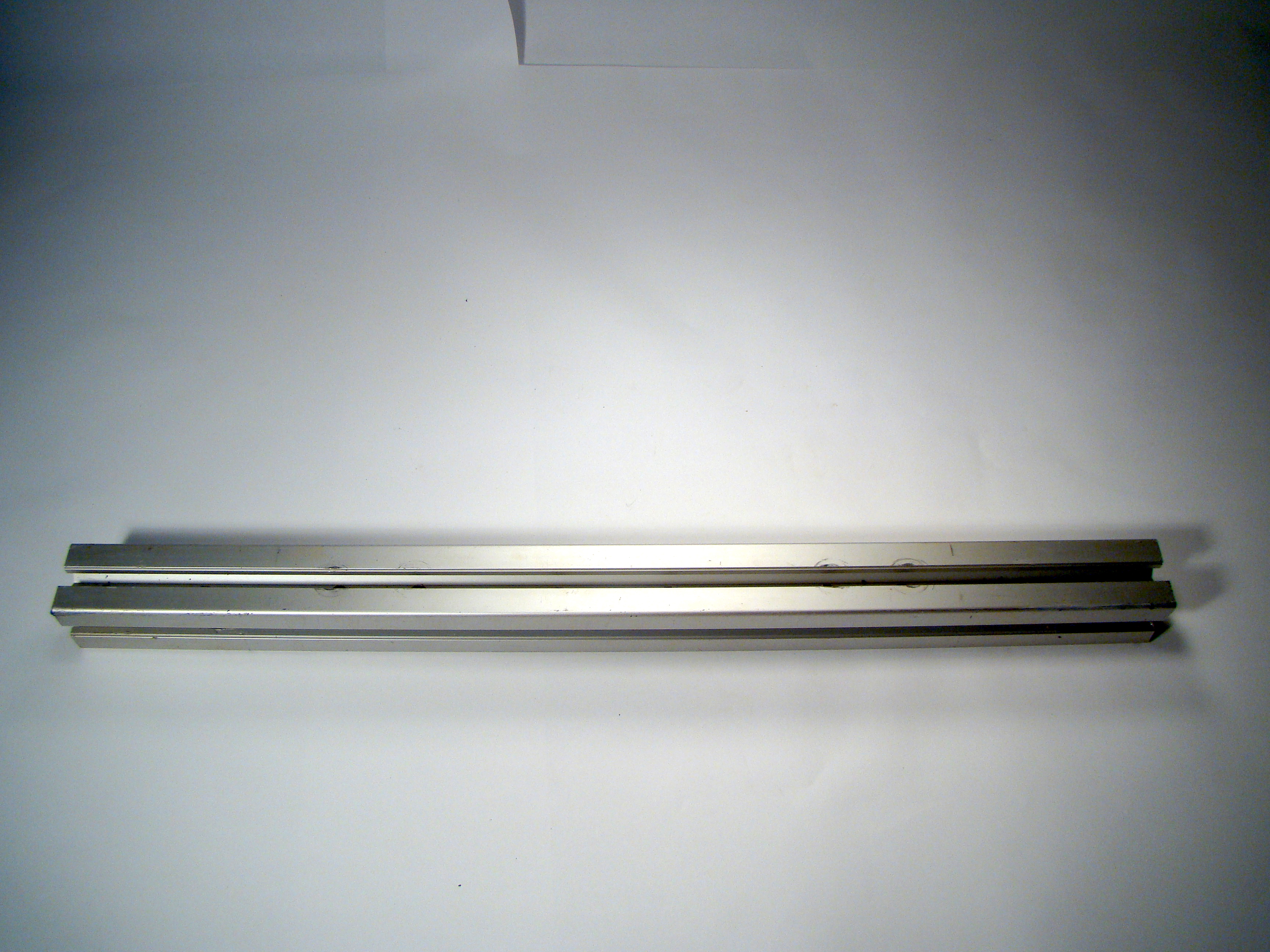
Backbone
The backbone provides the core structure of each track, and is made up of Aluminum T-slot Extrusion (chosen because of rigidity and lightness, and provides T-slots for tensioning). The extrusion is cut to length, and then holes are drilled into the extrusion.

- 6 riser block mounting holes vertically into extrusion
- 4 main track mounting holes vertically into extrusion (these are used in the final assembly of the tracks to the frame)
- 2 main drive-end mounting holes vertically into extrusion (these are for mounting the drive-end bearing blocks)
Guide Rail
The guide rail serves as a bearing surface for the conveyor chain (aka track), and is made of Ultra High Molecular Weight Polyethylene (UHMWP) conveyor guide material with a stainless steel backing channel. The guide rail is cut to the overall length, the metal is trimmed on each end, and the UHMWP (plastic) bent upward on each end to provide the proper approach angle of the chain to the idler and drive sprockets.


- To trim the metal from the guide rail, slide the plastic out one side of the metal channel, leaving approximately 6″ of stainless steel channel exposed on the other end. Cut off the exposed stainless steel channel, then slide and center the remaining stainless steel channel on the plastic, leaving approximately 3″ of bare plastic on both ends.
- To bend the plastic ends, clamp one end of bare plastic in a vise, and use a propane torch to carefully heat the plastic close to the stainless steel channel – do not melt! Bend the bare end of plastic toward the stainless steel channel to approximately 20°, as shown above. TIP: Slightly over-bend the plastic, and hold it in place until it is cool; or, you can pour water onto the plastic to cool it quicker. Once cooled and released, the plastic will spring back to the proper angle.
Repeat for the other end of the guide rail. Once both ends are bent, counter-sink the three riser block mounting holes, drilling from the plastic-side of the guide rail, and counter-sinking into the plastic so the riser block screw heads will be slightly below the surface.
Riser Blocks (3 per track)
The riser blocks (3 per track) provide space between the backbone and track chain, and are made of standard 2×4 (pressure treated or non-pressure treated) wood. TIP: It is best to use scrap wood to test for a proper fit, before using the actual 2×4 pieces. The proper fit should be a snug, slight press fit of the guide rail in the block groove.
Straight grooves are routed via the length of a 2×4, long enough to accommodate 6 riser blocks (3 per track × 2 tracks). Ensure a proper fit, and then cut all 6 riser blocks to length from the grooved 2×4. TIP: Only 3 riser blocks will be used per track, but I found that it was easier to test fit and cut all 6 at once, rather than going through the exercise twice.


Assemble Track Frame
To assemble the track frame, position the 3 riser blocks so that the grooves are down, and place the backbone on top of the 3 riser blocks. Align the front and end blocks so that they are coincident with the ends of the backbone, and the center block with the center of the backbone. Use flat head wood screws to attach each riser block to the backbone.
Once the riser blocks are attached to the backbone, gently (but firmly) press the guide rail into the grooves. Use flat head wood screws to attach each riser block to the guide rail, ensuring that the screw head is flush with the plastic surface.


Bearing Blocks (4 per track)
The bearing blocks secure the drive and idler shafts to the backbone, and are made of standard 2×4 (pressure treated or non-pressure treated) wood, and shielded, single-row ball bearings. The wood is cut into 4 pieces to length, and then holes are drilled into each block.
- 2 mounting holes (5/16″), with a 1″ diameter counter-bore for the mounting bolt pockets
- 1 drive/idler shaft bore (⅝”), with a 1-¼” diameter counter-bore for the bearing pocket


Chamfer the top and bottom corners of the bearing-ends of the block for chain clearance. Use a rubber mallet to tap the bearing into the bearing pocket, ensuring that the bearing is flush with the surface, tight in the pocket, and doesn’t slip. TIP: I had to tighten the bearing fit by wrapping the outside of bearing with electrical tape, and then pressing/tapping it into the pocket.
Repeat for each bearing block.
Sprocket and Hub Assembly
Sprocket (2 per track)
The sprocket aligns, secures, and transmits torque to the track chain, and is made of ½” Lexan (polycarbonate) — acrylic is too brittle for this application. Sprockets can be purchased, but I designed and cut these sprockets to specifically fit the track chain that I was using.

After determining the sprocket size and teeth-number and -spacing needed, I made a template and transferred it to Lexan. I then cut the Lexan using a drill (for the teeth) and a bandsaw. I cut out 8 sprockets total (4 per track). The Drive and Idler Sprocket and Hub assemblies are identical.
Hub (2 per track)
The hub transmits torque from the shaft to the sprocket, and is made of 6061-T6 aluminum with a 1/4-20 set-screw. Hubs can be purchased, but I machined these hubs to fit the sprockets and shaft I was using. After determining the bolt pattern needed for mounting the sprockets, I used a metal lathe to machine a flange in the aluminum, and drilled the 4 mounting holes through the flange. Then I drilled the ½” center shaft bore, and drilled and tapped the set-screw hole to the center shaft bore. I machined 8 hubs total (4 per track).

Assemble Sprocket and Hub
To assemble the sprocket and hub, slide a sprocket and hub onto a length of ½” rod, so that the flange is against the sprocket, then mark the 4 hub mounting holes onto the sprocket. Remove the sprocket, and drill the marked holes. Align the hub mounting holes to the holes in the sprocket, and from the hub side, push a 5/16″×1″ bolt through each hole; affix (in this order) a plain washer, lock washer, and standard nut on each bolt, and tighten.
Repeat for each sprocket and hub assembly.


Drive and Idler Shafts
The Drive and Idler Shafts are made of ½” diameter stainless steel (but could use mild/carbon steel). The stainless steel rod is cut to length, and then “flats” are machined along the side of each end for the pulley and hub placements. Flats should line up with the pulley and hub set-screw locations. TIP: Machining both flats or one long flat on both shafts would make them identical.


Assemble the Track
Drive End Bearing Block, Pulley, and Sprocket Assembly
The drive end bearing block, pulley, and sprocket assembly is comprised of a sprocket and hub assembly, 2 bearing blocks, a drive shaft, and a drive pulley. On the drive shaft, place a bearing block, a sprocket and hub assembly, and another bearing block, so that both bearings are positioned inward. Lock the hub to the drive shaft on the machined flat via the hub set-screw, and bolt the assembly to the backbone via the drive-end mounting holes on the bearing blocks.


For each 5/16″×5″ hex head bolt and ⅞” washer (there are 2 per block), affix (in this order) a ⅞” washer, lock washer, and standard nut, and then tighten. Mount the drive pulley to the drive shaft protruding from the inside bearing block (for left-hand tracks, the shaft will protrude from the right; for right-hand tracks, the shaft will protrude from the left). Lock the drive pulley to the drive shaft on the machined flat via the pulley set-screw.


Idler End Bearing Block, Brake-Pulley, and Sprocket Assembly
The idler end bearing block, brake-pulley, and sprocket assembly is comprised of a sprocket and hub assembly, 2 bearing blocks, an idler shaft, and an idler brake-pulley.
On the idler shaft, place a bearing block, a sprocket and hub assembly, and another bearing block, so that the both bearings are positioned inward. Lock the hub to the idler shaft on the machined flat via the hub set-screw, and from the outside of the bearing block, push a 5/16″×2″ hex head bolt with a 7/8″ washer through each of the mounting holes.
On the inside of the bearing block, affix (in this order) a ½”×½”×7/16″ square nut (or T-nut) to the end of each mounting bolt; leave the nut near the end of the bolt. Align the square nuts so that they can slide into the backbone’s T-slot, and slightly tighten the mounting bolts so that the bearing blocks can slide along the backbone’s T-slot.
Mount the idler brake-pulley to the idler shaft protruding from the inside bearing block (for left-hand tracks, the shaft will protrude from the right; for right-hand tracks, the shaft will protrude from the left). Lock the idler brake-pulley to the drive shaft on the machined flat via the pulley set-screw.


Mount and Tension the Track Chain
The track chain is comprised of a continuous loop of 52 “bottle” conveyor chain (Intralox 880T-K325) links. TIP: I originally thought that the links would have to be designed and machined by hand. This was a daunting task, so I was very pleased to discover that conveyor chain worked well as a tank track!

Slide the loop onto the track frame, seating the chain in the drive sprocket. Slide the idler bearing blocks toward the center of the track frame, allowing room to slide the chain onto the idler sprocket. Align the teeth of the idler sprocket with the inside of the chain.
TIP: This vehicle is driven from the fixed (non-tensioning) front end, and tensioned from the rear, non-driven end, which is also where the brake pulley is mounted.


To tension the track chain, use a rubber mallet to slide and tap each idler bearing block toward the rear to create the proper chain tension (tension is correct when the chain is about ¼” above the center of the backbone). TIP: It is helpful to slightly tighten the idler bearing block T-slot screws to have some friction for movement.


Once proper tension has been obtained, tighten the T-slot screws to keep idler bearing blocks in place. TIP: Although the “bottle” conveyor chain is forgiving with respect to tension, it is important that the chain not be too tight — this makes the drive too stiff.
To make the right-hand track, repeat all of the above except flip the drive and idler assembly.


