This is something that almost every maker that is interested in easy electronics should know how to do. It is great for decorating or just experimenting for starters.

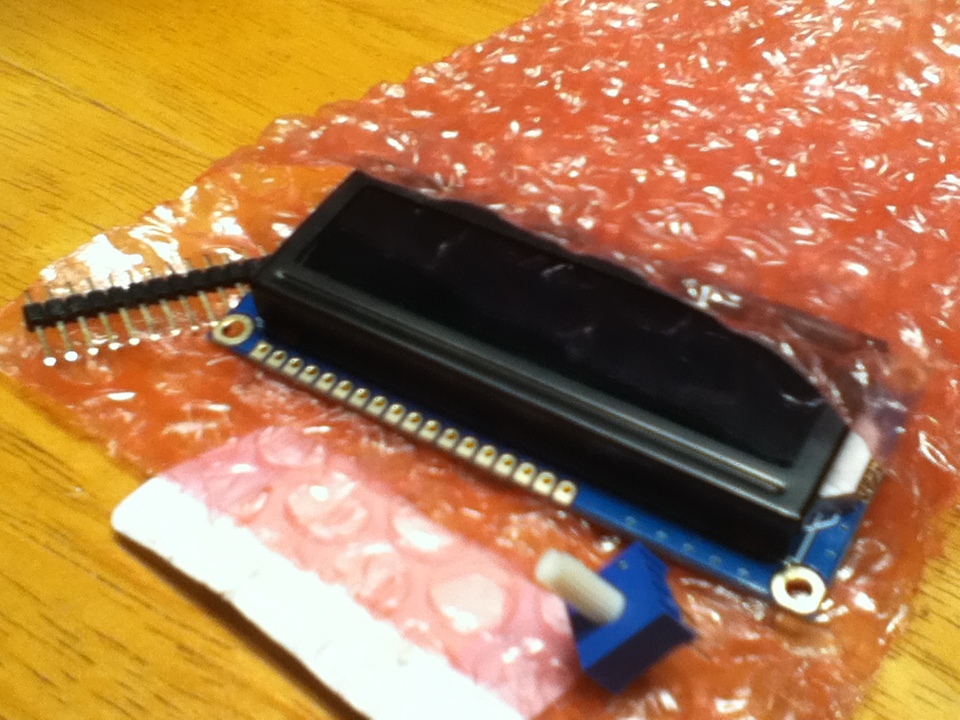
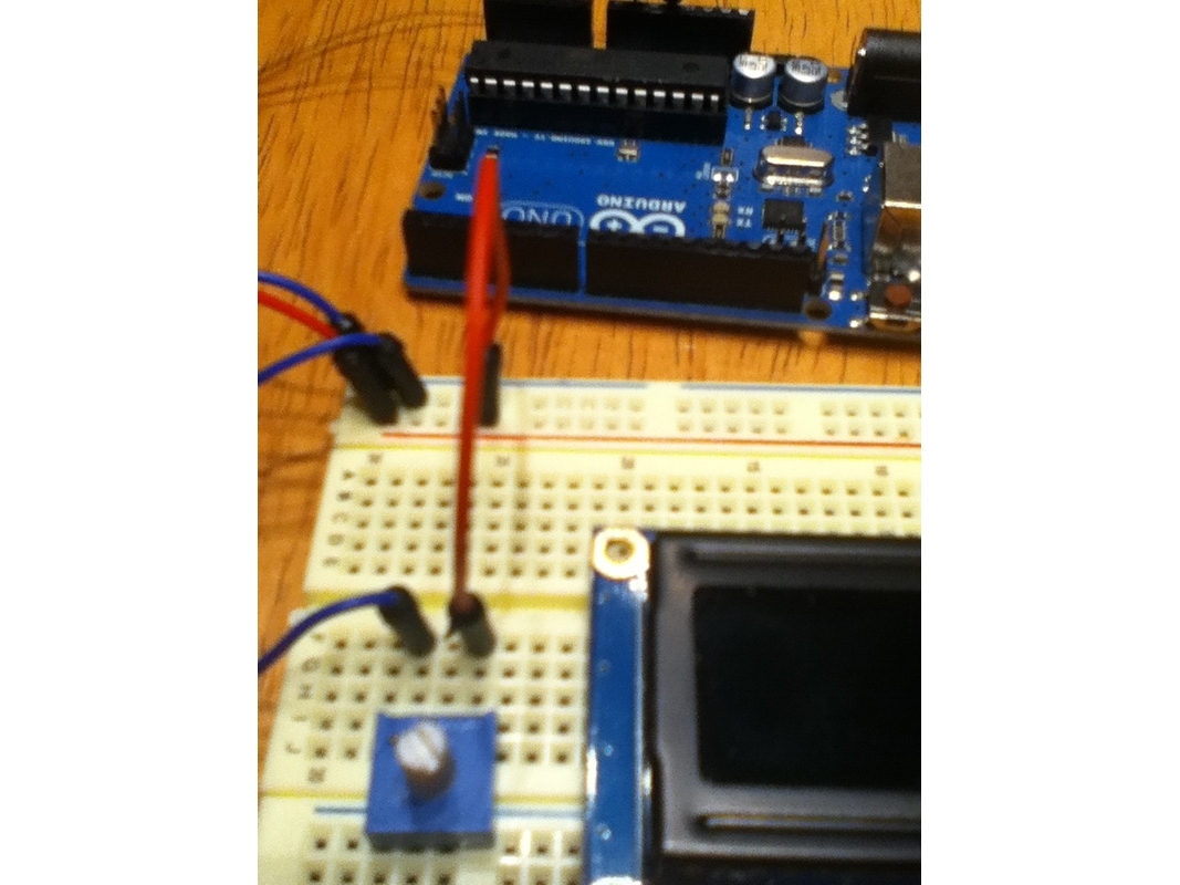
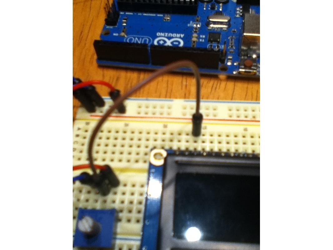
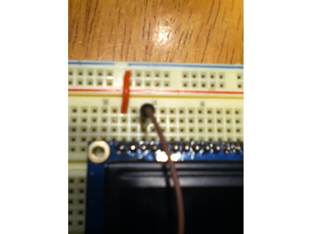
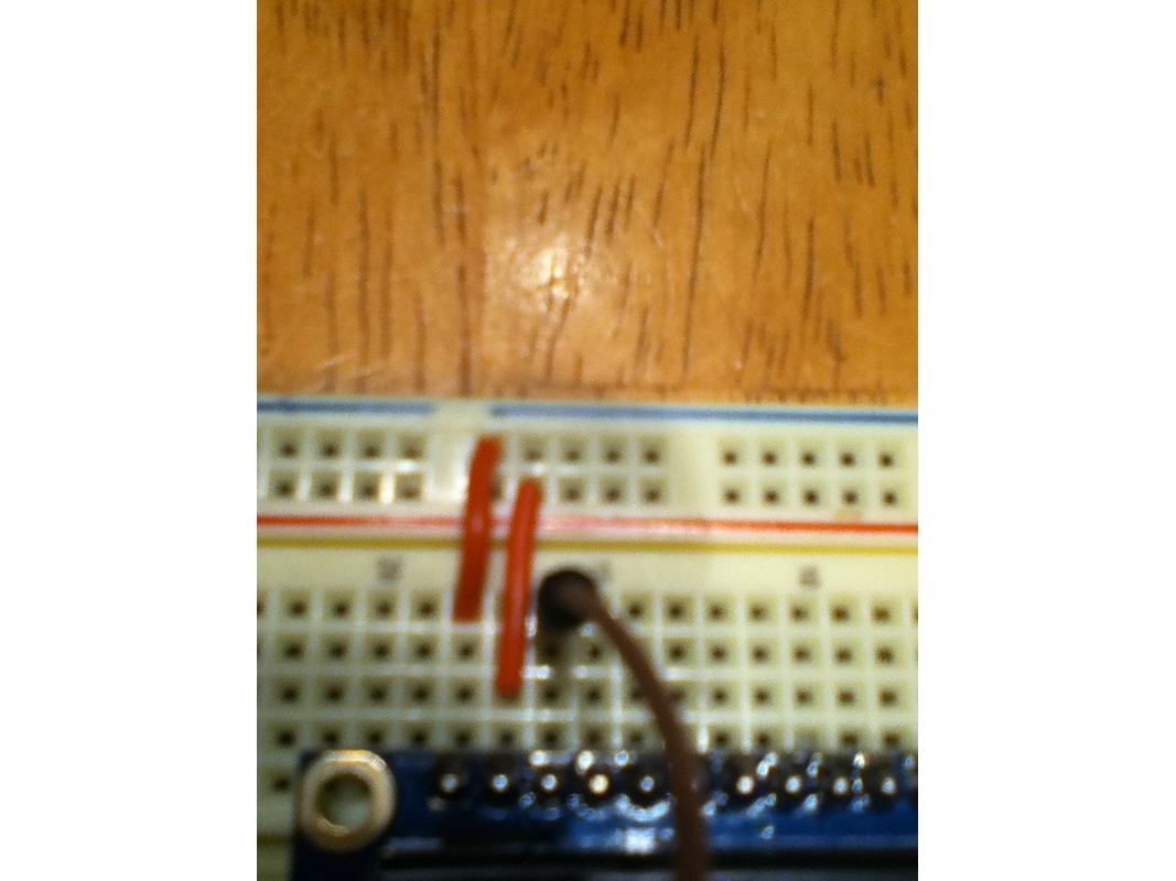
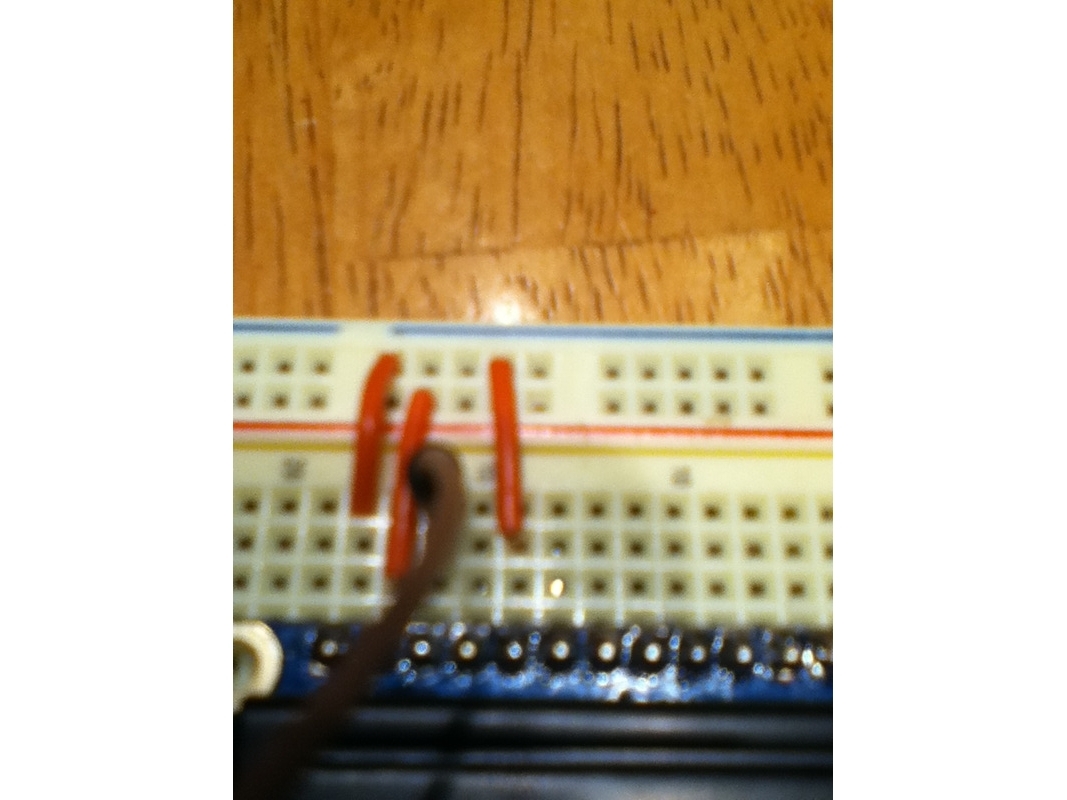
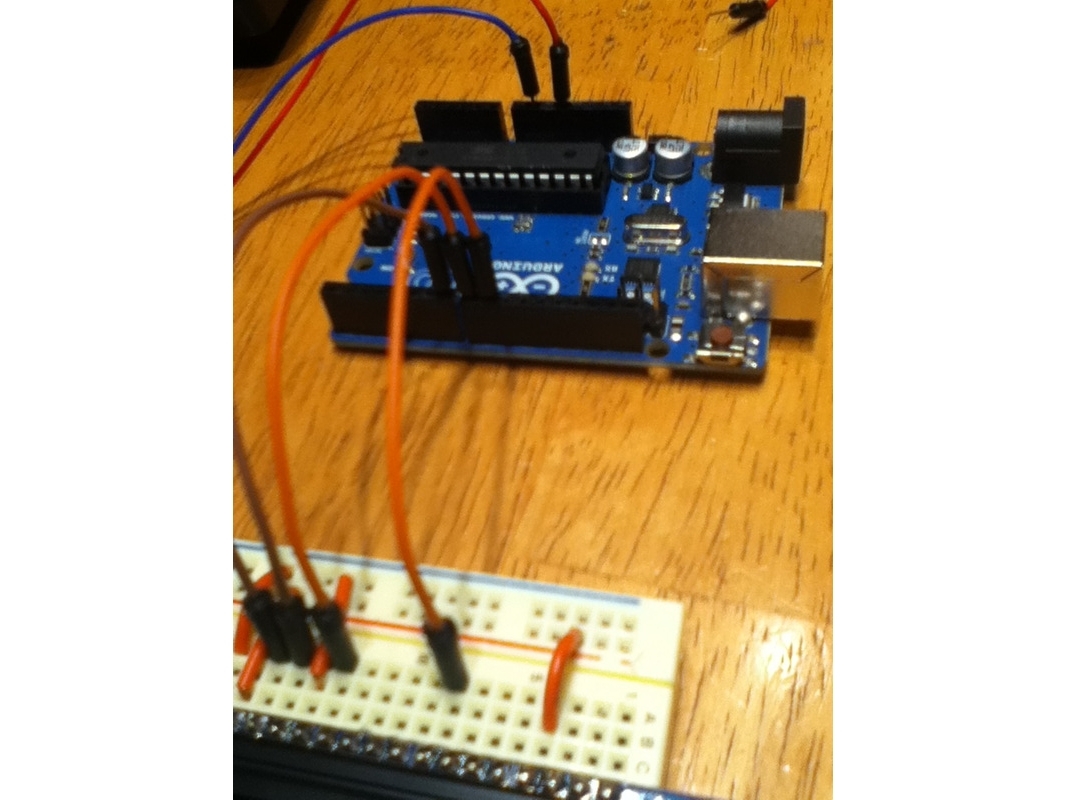
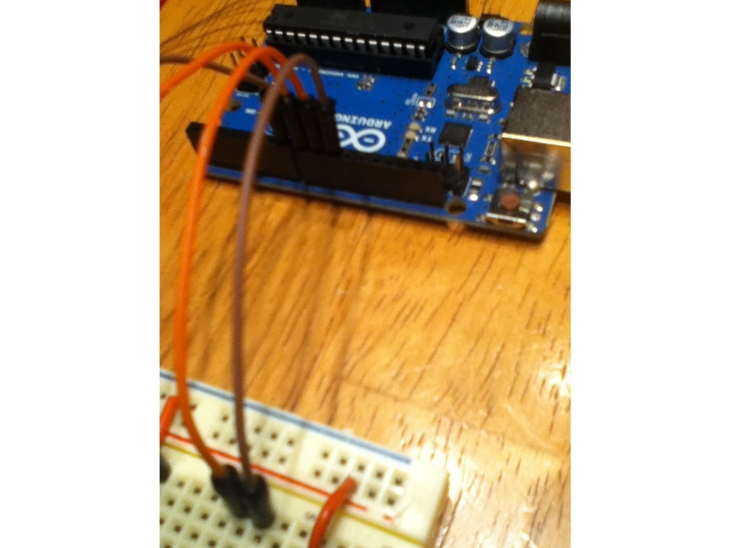
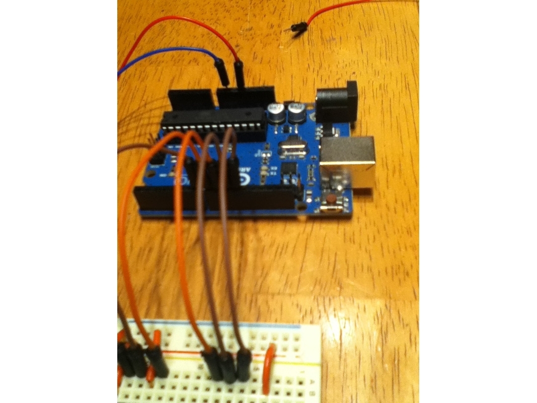
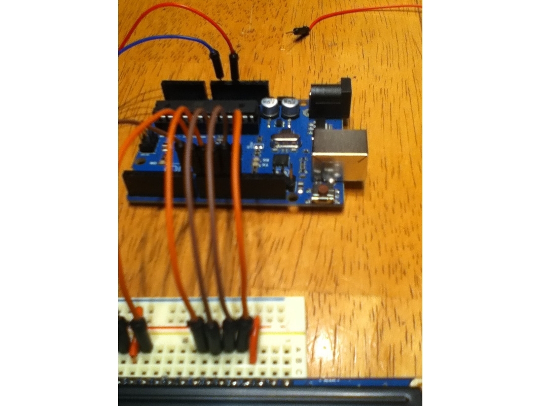
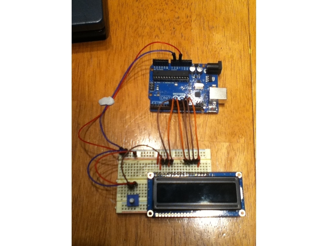
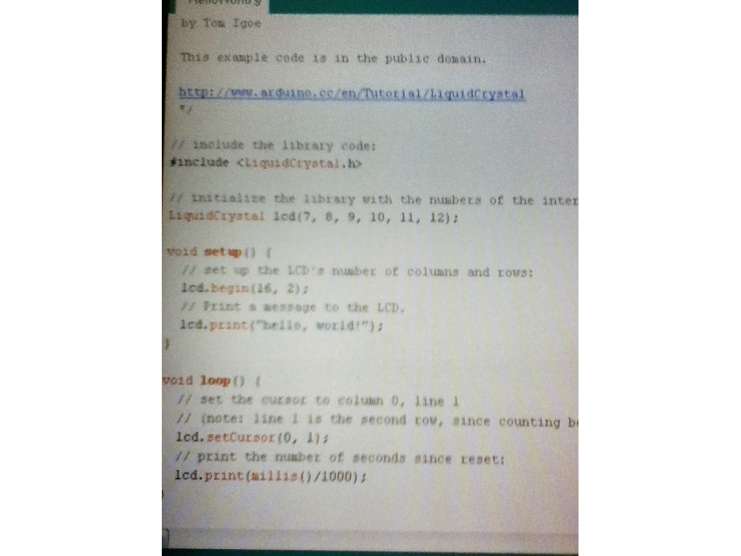
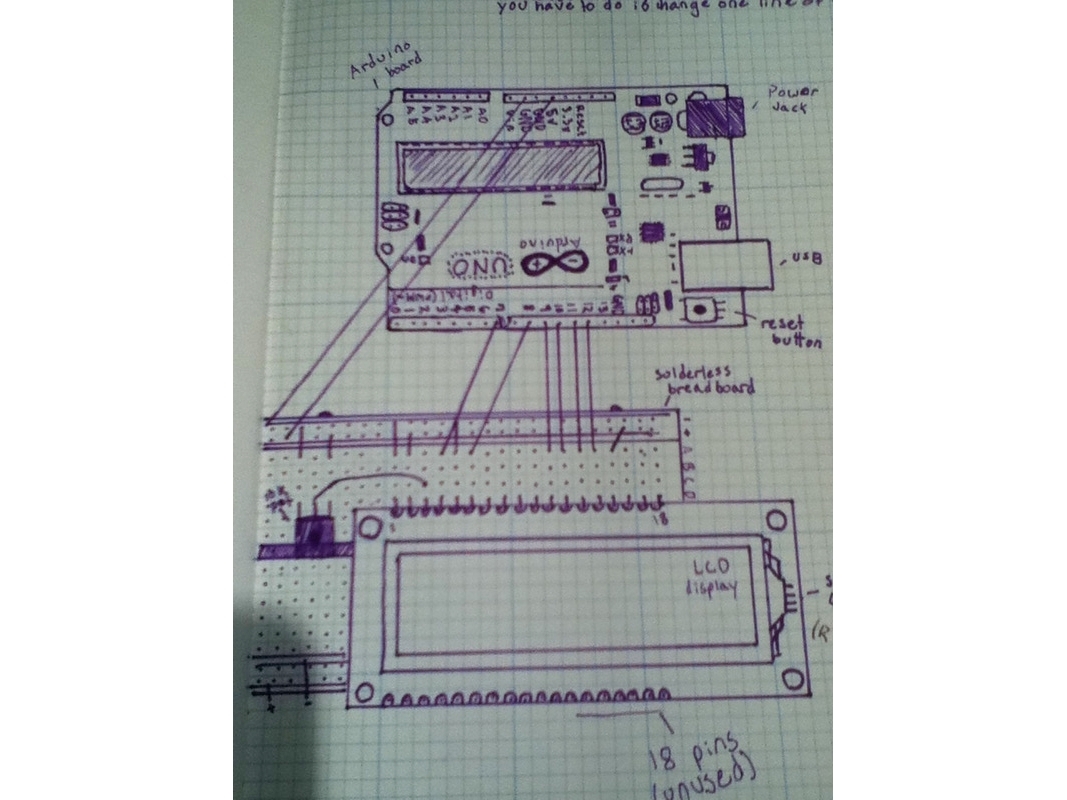
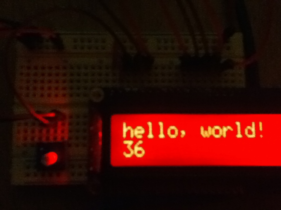
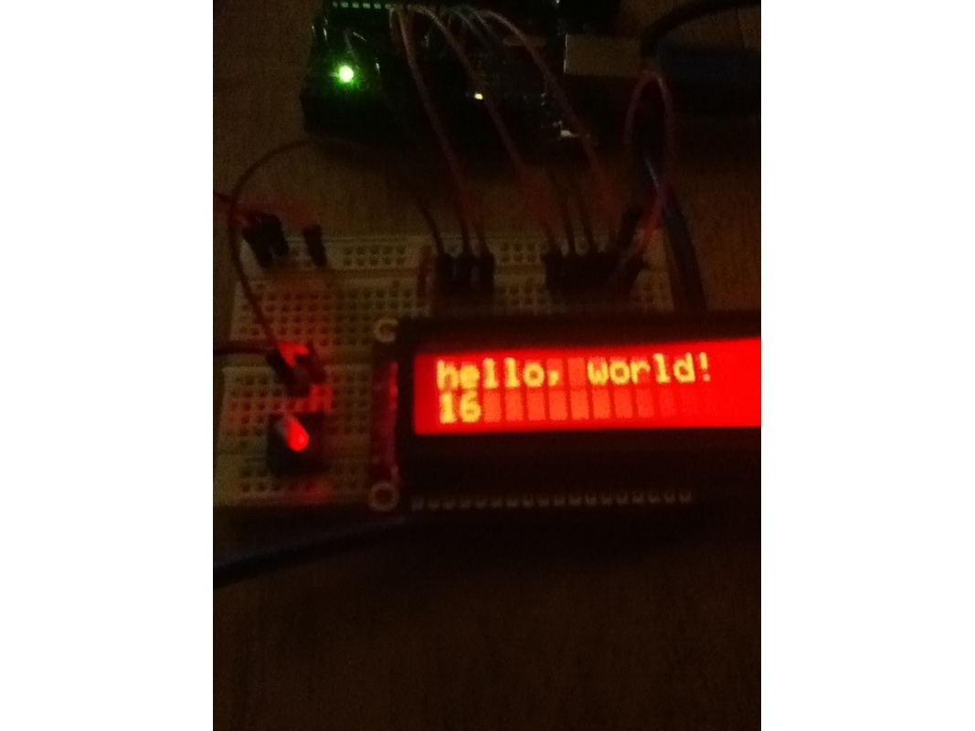
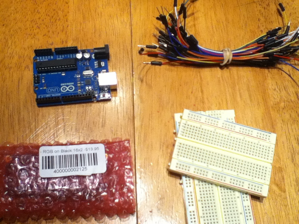
I am doing this tutorial because I had bought an RGB display from the Maker Shed and it was hard to track down the instructions. First I will teach you how to connect it to the Arduino and then I will show you the code required.

This isn’t my very own tutorial; I am just making the information easily accessible for everyone.

Project Steps

We will start off by gathering all of the parts together. Then open the package. Inside, you will find the display, contrast pot, and header pins. Solder the header pins on the same side that I did.

Now we will prepare everything to start connecting to the Arduino. Insert the display into the breadboard with the pot next to it. Then connect 5V and GND to the breadboard rails as I have done. Good.

Now we will hook up the contrast pot. Connect one side of the pot to GND and the other to 5V. Then hook the middle of the pot to pin 3 on the display.

Connect pin 1 of the display to GND, pin 2 to 5V, and pin 5 to GND.

Connect pin 15 to 5V and then connect either pin 16, 17, or 18 to GND depending on what color you want for your backlight. I picked pin 16 which will make it light up red.

Now we will start connecting the Arduino to the display. Connect pin 4 of the display to pin 7 on the Arduino; pin 6 to pin 8; pin 11 to 9; 12 to 10; 13 to 11; and pin 14 on the display to pin 12 on the Arduino.

The setup should look something like this.

Now you have connected the display to the Arduino. For the code, navigate in the Arduino environment to Examples→Liquid crystal→Hello world. Change the line of code that says: LiquidCrystal lcd(12, 11, 5, 4, 3, 2); to LiquidCrystal lcd(7, 8, 9, 10, 11, 12);.

A wiring diagram is included here.

If you got everything right, this is how it should look.

Conclusion

You have now just set up a liquid crystal display!