


In times like these you learn to … lather up. Everybody needs hand hygiene, everywhere. Most of us take it for granted but for some, it’s just not readily available.

LavaMaex is a nonprofit accelerator changing the way the world sees and serves our unhoused neighbors. Our goal is to teach the world how to take critical services to the street by providing free toolkits, mentorship, and training for communities that want to launch LavaMaex designed programs such as shower trailers and DIY handwashing stations. To date, we have inspired or directly advised 189 mobile hygiene programs around the world.
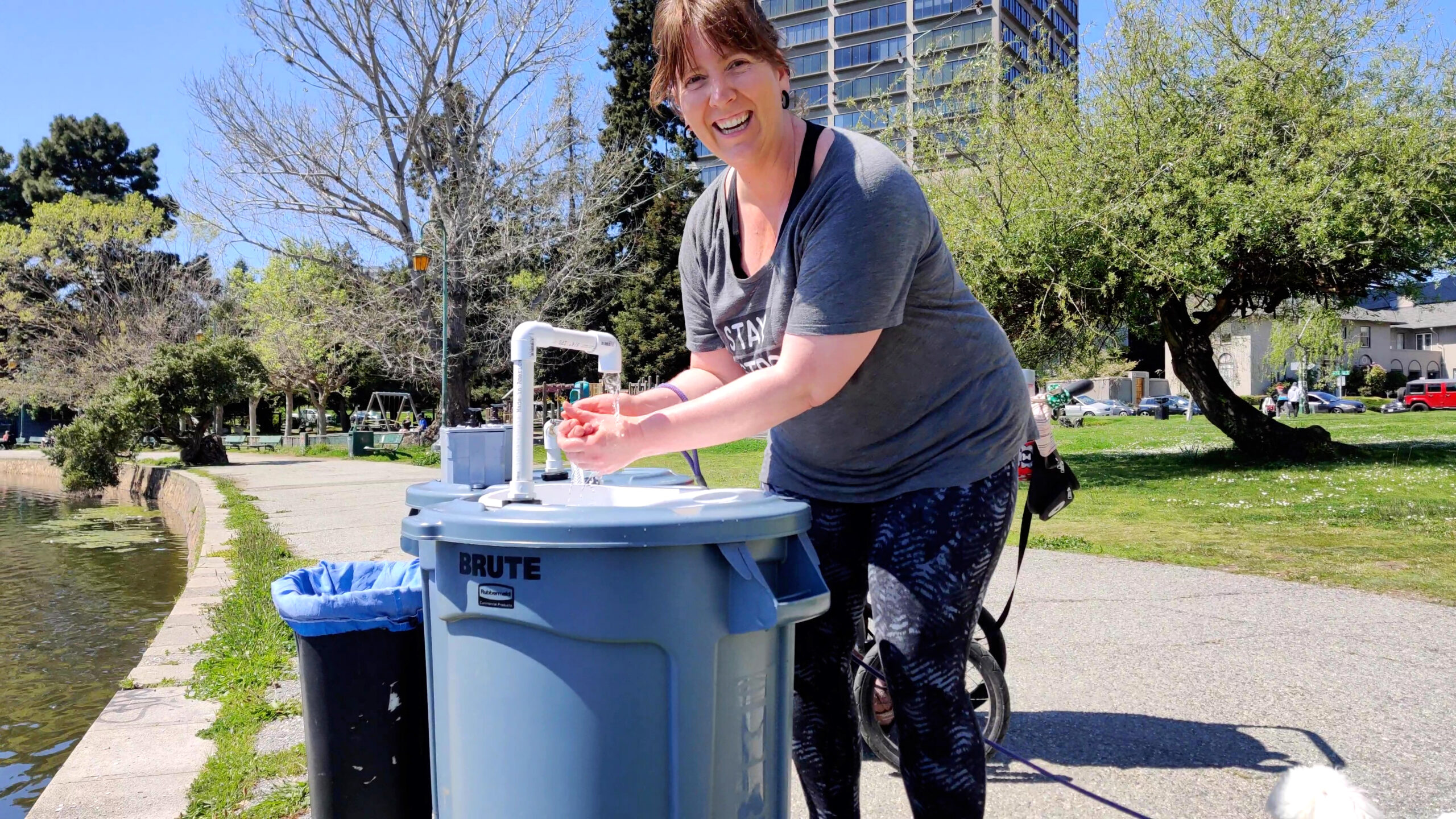
Inspired by Love Beyond Walls, and a grassroots campaign between USC Annenberg and Los Angeles Community Action Network (LACAN), we created this mobile handwashing station, designed for longevity, durability, and high capacity while creating opportunities for community connection and ownership of the units. Our DIY 32-gallon trash bin design is simple enough for anyone to assemble using tools and parts easily found at a hardware store, and it’s low-cost compared to commercial handwashing rentals. It can accommodate up to 500 handwashes at a time, and can be built, deployed, and maintained by the community.
Here’s how to build one for your community.
BUILD YOUR MOBILE HANDWASHING STATION
This is how we do it. Be sure to watch the DIY video tutorial and visit our website before you build, for updated parts lists and instructions.
1. BUILD THE FRESH WATER BIN
1a. Decide where you would like the plumbing to come out of the lid of your bin. In our bin, we chose the center. Once you’ve decided the location, use a ½” drill bit or hole saw to cut the hole.
1b. Separate the two pieces of a ½” bulkhead union washer fitting (Figure  A), leaving one washer per piece. Push the piece with the threading through the hole you have cut and screw the other side on, on the underside of the lid.

1c. Wrap a few layers of PTFE tape (Figure B ) around the threaded areas of two ½”×¾” PVC male reducer adapters (Figure C
 ).
).


1d. Screw the PVC reducers into the top and bottom sides of the bulkhead fitting.
1e. Cut a 3″ length of ¾” PVC pipe (Figure D ) and slide it into the PVC reducer that’s on top of the lid.

1f. Slide a ¾” PVC elbow (slip × FPT) (Figure E ) onto the 3″ pipe.

1g. Wrap a few layers of PTFE tape around the threaded areas of a ½” brass barb × ¾” MPT reducing adapter (Figure  F) and screw it into the FPT side of the elbow. Place the lid to the side.

1h. Measure the distance from the top of the bin to ½” above the bottom of the bin. Cut a ¾” PVC pipe to this length. Cut the bottom end of this intake pipe at an angle. You want it to stop ½” before hitting the bottom of the bin, to prevent sediment from being picked up by the pipe when pulling fresh water.
1i. Slide the non-angled end of the PVC pipe into the PVC reducer on the underside of the lid, then place the lid back on the bin.
TIP: To make sure the ¾” PVC pipe isn’t hitting the bottom of the bin, press on the lid and try to feel if the pipe is hitting bottom. You can also try lifting the lid on one side and peeking in. If it’s too long, simply cut it shorter with the PVC cutter
2. DISHPAN CUTOUT AND FAUCET
2a. We recommend placing the 12qt dishpan (Figure G ) centered on the lid, but slightly forward, closer to where the guest will be washing their hands. This gives ample room for the dishpan and faucet. With a marker, trace the circumference of the sink basin on the top of the lid; you will be cutting along this line. Place the dishpan aside.

2b. Use a handsaw or a Dremel equipped with a plastic cutting wheel to cut along the traced line on the lid. You may need to trim the hole slightly a few times in order to get it just right. The dishpan will not be glued in, so the goal is to get it to sit comfortably and securely in the lid while allowing easy removal for access to eliminate the greywater that will fill this bin.
2c. Place the faucet to the rear of the dishpan. There should be just enough room; approximately ½” between the dishpan and the faucet (another ½” bulkhead fitting). Use the drill with a ½” hole saw to cut the hole for your faucet (Figure H ).
).

2d. Install the bulkhead fitting into the ½” hole you drilled.
2e. Wrap a few layers of PTFE tape around all threaded parts of two more ½”×¾” PVC male reducers, then screw one into the top and one into the bottom of the bulkhead fitting.
2f. Cut a length of ¾” PVC pipe at the desired height for your faucet.
2g. Slide this pipe into the PVC reducer on top of the lid.
2h. Slide a ¾” 90° PVC elbow (slip × slip) (Figure  I) onto the pipe.

2i. From the curved portion of elbow, measure the horizontal distance to the drain, then use that measurement to cut a short length of PVC pipe.
2j. Slide this pipe into the elbow horizontally.
2k. Slide one last 90° PVC elbow (slip × slip) onto the open end of the horizontal pipe to complete the faucet.
3. INSTALL THE DRAIN
The drain we used (Figure  J) separates into upper and lower pieces so that the dishpan “sits” between the two.

3a. Find the upper drain piece that will go through the sink basin, place that portion in the center of your dishpan, and trace its circumference onto the bottom of the dishpan.
3b. Use the handsaw or Dremel to cut along the traced line.
3c. Insert the upper part of the drain through the hole (Figure K ), then screw on the lower part on the underside of the dishpan (Figure
  L).
L).


3d. Slide the 2″ ABS 90° elbow (Figure  M) into the opening at the bottom of the drain, underneath the sink basin.

4. INSTALL THE PLUMBING
In our model, the plumbing exits at the front of the greywater bin. It’s very important that the ¾” in-line check valve sits in a horizontal position. Your PVC piping also needs to go low enough in the bin to avoid touching the sink basin, drain, and elbow. Assuming your model will mirror ours, install plumbing as follows.
4a. Measure from the top of the sink basin to the lowest part of the 2″ ABS 90° elbow.
4b. Add 1″ to 2″ to this measurement, and cut a piece of ¾” PVC pipe. Insert that piece into the PVC reducer that’s screwed into the bulkhead on the underside of the lid.
4c. Slide a ¾” 90° PVC elbow (slip × slip) onto the end of the PVC pipe. The open side of this elbow should be facing the direction in which the plumbing will exit the unit.
4d. On the front of your bin (Figure N ) where the plumbing will exit, use your measurement from step 4b to measure from the top of the bin, down toward the ground. Place a mark with a marker.

4e. Tip the bin on its side and drill a ½” hole at your mark.
TIP: To prevent the bin from moving when drilling, position the bin so that the opening is facing you, and use one foot to step on the inside of the bin.
4f. Install the remaining ½” bulkhead into the hole. Wrap a few layers of PTFE tape around the threads of the remaining two PVC male reducers and screw one into either side of the bulkhead.
4g. Cut a 3″ length of PVC pipe and slide it into PVC reducer on the inside of the bin.
4h. Slide the ¾” in-line check valve (Figure O ) onto this pipe.

IMPORTANT: There’s an arrow on the in-line check valve; make sure this arrow is facing the faucet. The purpose of the valve is to prevent backflow of water inside the unit. If you install it backward it will prevent water from entering the bin properly and coming out of the faucet.
4i. Measure from the center of the check valve to the curved portion of the elbow from step 4c.
4j. Using that measurement, cut another ¾”
PVC pipe.
4k. Slide one end of this pipe into the check valve, and the other end into the elbow from step 4c. This completes the plumbing inside the greywater bin.
NOTE: If the ¾” PVC pipe from this step is too long, trim it down a bit to ensure a proper, comfortable fit between all connections and pieces (Figure P).

4l. Cut a 3″ pipe and slide it into the PVC reducer that’s screwed into the bulkhead outside the bin.
4m. Slide a ¾” 90° PVC elbow (slip × FPT) onto the 3″ pipe.
4n. Wrap a few layers of PTFE tape around the MPT threads of the remaining brass barb reducer and screw it into the FPT end of the elbow.
5. MAKE THE SOAP DISPENSERS
5a. On the lid of your freshwater bin, decide where you’d like to place the two electrical junction boxes (Figure  Q). Make sure they’re level, and accessible to the user washing their hands. We recommend placing them on the side nearest to your handwashing / greywater bin.

5b. With the boxes in place, use a marker to mark through the two mounting holes for each, then place the boxes to the side.
5c. Drill four ¼” holes through the lid at your marks. Make sure the ¼-20 bolts fit through the holes.
5d. Put the boxes back on the lid in the correct position, making sure the mounting tab holes line up with the holes in the lid.
5e. Push the four ¼-20 bolts (Figure R ) through the attachment tab holes and the holes in the bin lid.

5f. Take the lid off of the bin and turn it sideways, so you can screw the nuts (Figure S ) onto the bolts. Tighten as much as you can by hand.

5g. Use a wrench to hold the bolt head (above the lid) and a socket wrench with ¼” socket to tighten the nut (underneath) as much as possible.
NOTE: We recommend nuts and bolts instead of glue for durability. You can add washers inside to make it even stronger.
5h. Stand your soap dispensing pump (Figure  T) inside the empty electrical junction box to determine how much, if any, of the straw on the pump needs to be cut. We removed about 2″ of the straw from The Right to Shower dispensing pump so that the straw stopped ¼” above the bottom.

5i. Drill a ¼” hole through the center of the lid of the junction box lid to allow placement of the soap pump, then glue the pump in place using a caulking gun and clear silicone adhesive.
5j. Once the adhesive fully dries (check instructions), fill the junction box with 32oz of soap. Then, using a Phillips screwdriver or bit, tighten all four screws to attach the lid onto the box (Figure  U).
U).

6. CONNECT THE BINS VIA GALLEY PUMP
6a. With the PVC cutting tool, cut a length of vinyl tubing (Figure  V) to go from the brass barb on the front of the greywater bin to the galley pump (Figure W
 ) on the ground.


6b. Slide two loose hose clamps (Figure x ) onto the tubing and let them stay loose for now.

6c. Attach one end of the tubing to the brass barb on the greywater bin, and the other end to the galley pump outlet connection.
6d. Slide two loose hose clamps onto the remaining tubing. Slide this tubing onto the inlet portion of the galley pump, and onto the brass barb on top of the freshwater bin.
6e. With a slotted screwdriver or bit, tighten one hose clamp over each barb and pump connection.
7. TEST AND GLUE
7a. Test your handwashing station by putting water in the freshwater bin and washing your hands. Make sure all parts and plumbing are working properly, and check for leaks (Figures Y and
and  Z).
Z).


7b. After everything operates perfectly, apply PVC cement glue to all slip joints (Figure  Aa); for example, where a ¾” PVC pipe slides into a PVC reducer or into the check valve.

7c. Apply ABS cement to the portion of the 2″ ABS elbow that slides into the sink drain.
7d. Apply clear silicone caulking to both sides of the washers/gaskets on the bulkhead fitting at the front of the greywater bin, for a leakproof seal.
7e. Put each bin on its dolly (Figure Bb ) and you’re done.

A LATHER OF LOVE
Communities around the world need broader access to handwashing and mobile sinks. Encampments, reservations without plumbing, rural outdoor living areas, shelters, churches, and city parks are just a few examples. Our goal is to meet those needs, or to be the hand that helps someone else do so. We’re all in this together.
Please share your story with us! We’d love to hear your experience of implementing this project in your community. Questions, concerns, and suggestions are always welcome here.


