I have always hated mowing the lawn. I was the guy who only mowed when the grass got to be 6″ taller than the neighbors’ lawns — not because I don’t like my neighbors, but because mowing was such a pain. After being hit by one too many rocks, I decided I no longer wanted to stand behind a mower while cutting the grass. I also realized that if I got a riding mower, I’d still be right in the middle of all that dust and pollen.

I started thinking, what if I could mow the grass from the back deck, or even the computer? To handle my 1-acre backyard’s hills, dips, and rocks, an R/C lawn mower would have to be very sturdy, be controllable from a good distance, and have enough battery power to last several hours. I built the Lawnbot400 to meet these criteria.

Resources

Functional Overview

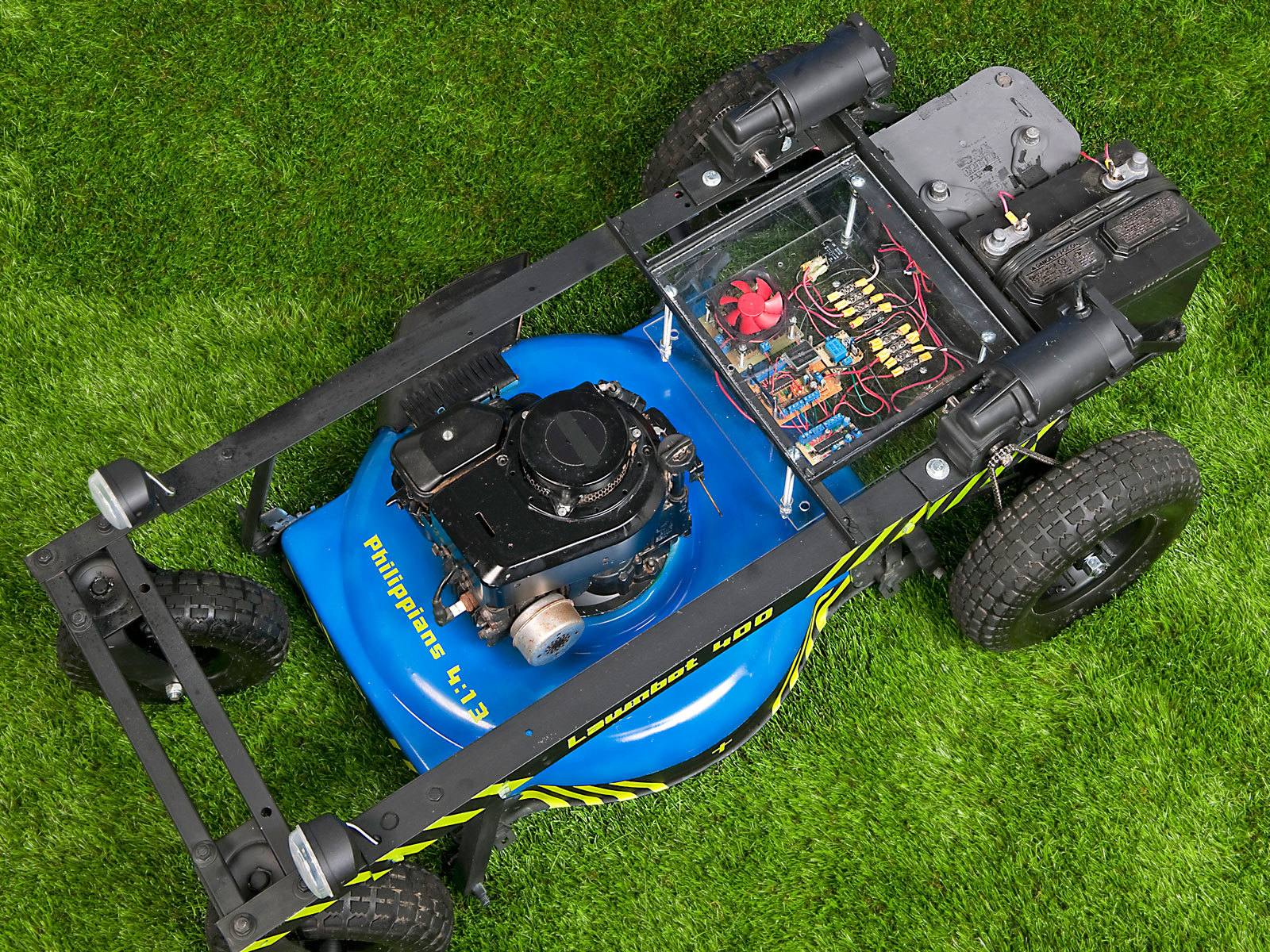
Basically, if you took the wheels and handlebar off any old gas-powered push mower, bolted it into a sturdy metal frame with 2 electric wheelchair motors, and added the electronics needed to make it move, you’d have the Lawnbot400. I control mine with a standard hobby R/C transmitter and receiver, but with just a few modifications it could be made autonomous.

Steering the Lawnbot is simple. Move the left control stick up, and the left wheel moves forward. Move the right control stick back, and the right wheel moves backward. Both sticks forward and you go straight ahead. This is called “tank steering,” and it gives the Lawnbot400 a zero turn radius.

The pieces that enable this control are a bit more complex. The hobby R/C transmitter encodes the control sticks’ positions and sends them to the receiver using pulse-position modulation (PPM), which encodes a value, such as the desired position of a servo, as the ratio of ON time to OFF time in a fixed-duration series of repeated pulses. But the H-bridge motor controller that supplies variable voltage to the wheelchair motors needs a simpler pulse-width modulation (PWM) signal, in which the pulses don’t repeat within a fixed time frame. So I used an Arduino-based microcontroller to translate the PPM R/C signal into PWM for the H-bridge.

The H-bridge uses transistors to convert the 0V–5V PWM values into straight 0V–24V DC voltages running from the batteries to the motors in both directions. The wheelchair motors are electric, so the bot will drive even if the gas-powered mower isn’t running. Instead of buying an H-bridge, I chose to build my own. (It should be noted that I didn’t plan to take the easiest route in this project. Instead, I wanted to learn how each electronic part worked, so I’d know how to fix it if it broke.)

I didn’t want to donate my Arduino to the project, so I made my own controller with screw terminals on each pin for secure connections during bumpy rides. Like an off-the-shelf Arduino, this board serves as a breakout board for the ATmega168 microcontroller chip, and it has its own 5V regulator (LM7805), 16MHz crystal, power LED, and reset button. I also added a header to the board for my R/C receiver to plug directly into. My board lacks the standard Arduino programming port and FTDI USB chip, so to use it, I simply program an ATmega chip in my Arduino, then swap it over.

With all of the above, I got the Lawnbot400 running successfully, and in the next version, I added a fail-safe to keep the bot from running away if it loses its signal. The fail-safe uses a second (even simpler) Arduino-compatible breakout board to read a third R/C channel, controlled by a toggle switch on the transmitter. The code reads this channel using the PulseIn method and sets a digital output pin accordingly. If signal is present, the output pin stays on, which uses a 5V relay circuit to keep a 60-amp relay open, to let the main 24V battery power reach the motor controller. But if the bot gets out of range or the switch is turned off, the channel reads LOW and motor power shuts off until signal is restored.

Both the R/C and fail-safe control boards were simple to build and cost around $12 each. Later, I figured out how to add fail-safe handling into the main R/C code, so you could use just one microcontroller chip with all 3 channels, but this would sacrifice some safety. If the sole ATmega goes crazy and stops responding, you’re out of luck, whereas it’s highly unlikely that both chips will fail at the same time. So I still use the separate, dedicated fail-safe.

Here’s how I built my latest Lawnbot400; see the Substitutions box on the previous page for easier options that will have you mowing from your deck chair sooner.

Project Steps

Make the controller boards (optional).

You can use 2 Arduino boards (or just one) for the R/C and fail-safe controllers, but here’s how I built my own simpler and semi-ruggedized versions cheaper. The fail-safe is optional but strongly recommended for safety. Get the code from this zip file.

The fail-safe board simply breaks out the pins from the Arduino’s ATmega chip to screw terminal blocks at the edges of the board. I put in a few capacitors for the 7805 voltage regulator and a crystal oscillator for the external clock, and that’s it. The fail-safe relay and fuse are too large to fit on the board but can be mounted nearby.

See reference #1 in photo: Pins 23–28 of the ATmega go directly to screw terminals for analog pins 0–5.

2-3: Pins 15–19 of the ATmega go directly to screw terminals for digital pins 9–13 (from right to left). The power LED is tied to +5V and a 330Ω resistor to ground.

4: The reset button goes from ground to pin 1 of the ATmega. Pin 1 also needs a 10K pull-up resistor. If you don’t want a reset button, put a 10K resistor from pin 1 to +5V.

5: Pins 7, 20, and 21 are tied to +5V. Pins 8 and 22 are tied to ground.

6: The power supply consists of a 7805 5V regulator, 2 capacitors, and a screw terminal. The 7805 can accept up to 36v dc input and will deliver 5V to the ATmega. The green capacitor is a 0.1µf decoupling capacitor and the larger blue one is a 220µf 10V.

7: Pins 2–6 of the ATmega go directly to screw terminals for digital pins 0, 1, 3, and 4.

8: The 16mhz crystal resonator goes to pins 9 and 10 of the ATmega (center pin of the resonator to ground).

9: Pins 11–14 of the ATmega go directly to screw terminals for digital pins 5–8.

10-11: Pins 23–28 go to screw terminals for analog pins 0–5. The first 6 screw terminals go directly to the 6 channels from the R/C receiver. None of these wires are connected to the ATmega. You must route the wires from these screw terminals to the desired ATmega pin’s screw terminals.

12: These 2 screw terminals are connected to the 2 sets of male servo pins below. The top pin is signal, middle pin is +5V, and the bottom pin is ground.

13: This header is for the R/C receiver. The top row breaks out each channel to a screw terminal. The second row is +5V. The third row is ground.

14: The reset button goes from ground to pin 1 of the ATmega. Also use a 10K pull-up resistor from pin 1 to +5V.

15: 16MHz crystal resonator to pins 9 and 10 of the ATmega.

16: Two LEDs with 330Ω resistors from digital pins 12 and 13 to ground. I use these as neutral indicator lights. When the control sticks are centered, these lights come on, which helps when fine-tuning the R/C transmitter. I sacrificed any other use of these pins for the LEDs.

17: The power supply: a 7805 5V regulator, screw terminal, and 2 capacitors. I put in several capacitors I had lying around (they must be above 10V rating), but it only needs a 220µf capacitor at the output and a 0.1µf decoupling capacitor close to the ATmega. If you’re not using bulk capacitors in your motor controller, use several here. I also added a 1N4001 diode to protect against reverse polarity.

18: Screw terminals for digital pins 2–11. I don’t use digital pins 0 and 1 on this board, and pins 12 and 13 are being used by the 2 neutral indicator LEDs.

The R/C controller uses a slightly larger piece of RadioShack perf board to carry the same components as the fail-safe board, plus 2 LED motor indicators connected to digital output pins 12 and 13, and a port for the R/C receiver consisting of three 6-pin female headers stacked together.

The control pins from this R/C port connect to another screw terminal block on the board. I could have simply used jumper wires to connect the R/C receiver to power and to the microcontroller, but the header and screw terminals make the connections stronger and very easy to reconfigure.

The 6×3 grid of connector pins on my R/C receiver are mapped with the first row of pins carrying each channel, the second row all +5V, and the third row all ground. You want to find 2 channels that are controlled by up/down movements on your transmitter, such as the ones used for throttle and elevation.

To do this, go down the line plugging a servomotor into each channel. Move every control stick until the servo moves, then write down which channel is controlled by what stick. Decide which 2 channels to use for the Lawnbot motors.

Connect these 2 channels on the R/C receiver to pins 4 and 5 of the microcontroller chip (which function as Arduino digital pins 2 and 3, the only 2 external interrupts). For the receiver’s power, I jumpered wires over from my Arduino-based R/C controller’s +5V and Ground pins.

Load and test the code.

Download the code and load it onto your Arduino(s). To check the R/C code from your computer, keep the Arduino plugged into the USB port, connect the R/C receiver as in Step 4, turn the transmitter on, and click on the Serial Monitor button in the Arduino IDE. Moving the left control stick should change the reading for your left motor’s channel, and the right stick should control the right channel. If not, swap the inputs.

The on-pulse duration readings should range from 1,000 to 2,000 microseconds, showing 1,500 when the control stick is centered. If not, adjust the stick’s trim control on the transmitter, or change the max and min values in the code to match the range of readings you see in the serial monitor.

If you’re in the field using standalone controller boards, you can use a multimeter to probe the Arduino pins’ voltage outputs while moving the control sticks. Arduino digital pins 5 and 9 (ATmega chip pins 11 and 15) run forward and reverse for left motor, and digital pins 6 and 10 (chip pins 12 and 16) control the right. Probe the pins one at a time, checking for a good 0V–5V PWM signal. Or use LEDs for a quick visual test; place them short leg to ground, long leg to the Arduino output pin, and look for the control stick to work like a dimmer.

Build the H-bridge (optional).

You can buy an H-bridge motor controller like the Sabertooth 2×25 from Dimension Engineering, but if you feel like an adventure, build your own. Here’s how I built one on a custom PC board for about $35.

Download the circuit board layout and schematic files triple8.brd and triple8.sch files both here. Also download Eagle from cadsoft.de; the free version is fine.

Open triple8.brd in Eagle and use a laser printer to print only the bottom layer on a piece of glossy magazine paper. I have tried many types of paper, and had the best results with my wife’s Cosmopolitan magazines. Find pages with plain black text only, like the backs of prescription drug ads, where they list the side effects. Feed the page into the printer manually to make sure it goes in straight.

Turn your iron to its high setting. Scrub the PC board’s copper side with a Scotch-Brite pad and clean it with acetone and paper towels several times.

Place the print facedown on the copper-clad board and place the iron on top. Apply pressure and heat for about 3 minutes, moving every 30 seconds. Let the board sit for a few minutes, then soak it in a bowl of warm, soapy water for 30 minutes. After soaking, rub the paper off with your thumb until only black toner traces remain.

Mix an etchant solution with 2 parts hydrogen peroxide to 1 part muriatic acid. Pour the etchant over the copper board in a glass dish and agitate it for about 10 minutes with a plastic implement or air pump. When the unmasked copper has all dissolved, rinse off the board and remove the black toner with more acetone and paper towels (photo).

Always wear chemical gloves and safety goggles while working with etchant, and take care not to drip or splash.

Drill holes in the PCB at every hole location. Solder the components on the board, following the schematic. Start with the resistors and terminals, and finish with the transistors and capacitors, making sure all the transistor gates point toward the resistor networks that drive them.

Finally, attach heat sinks to the 47A and 52A transistors and bolt a PC cooling fan on top, aimed to draw air away from the board.

To test your H-bridge, hook it up to a 12V power source, following the schematic. Apply your Arduino’s 5V to each input, and use your voltage meter to look for 12V at the 2-pole motor terminal outputs.

Mount the wheel sprockets.

The easy way is to find a set of wheelchair motors that have wheels already mounted. I couldn’t find any in my price range, so I just went with the motors and found my own wheels. I didn’t think the motors would be strong enough to drive the wheels directly, so I opted for a 17:65 chain drive.

To mount the sprockets to the wheels, I drilled matching sets of 3 holes aligned around the centers of the drive wheels and the 65-tooth sprockets. Then I bolted the sprockets on and tightened them up against the inside hubs as much as possible. I also welded the sprockets to the hubs to keep them centered. Welding isn’t necessary, but it helps.

Build the frame.

I made a simple rectangular frame and suspended the lawn mower body underneath it using 4 lengths of angle iron bolted to the mower’s original axle holes. You’ll want to custom-size your frame to fit your particular mower, and if something doesn’t line up exactly, you may have to use your creativity. Luckily, the dimensions don’t all have to be perfect.

Begin planning your frame by measuring your lawn mower’s footprint and height. The frame’s width should match the mower’s original wheelbase, and its length must let the front caster wheels swing 360° without hitting the mower deck. Its height should allow you to adjust the deck to sit at its original height range. For my frame, this meant 24″ wide by 48″ long by 18″ tall.

I constructed my frame by cutting, drilling, bolting, and welding together lengths of angle iron, square tubing, threaded rod, and flat steel. The main part of the frame consists of 2 long pieces of 2″ angle iron that run from front to back, one on each side. In front, these runners are bolted to 2 crosspieces of square tubing, which in turn bolt to the mounting plates of the 2 caster wheels.

In back, the left and right runners are held up level by vertical angle-iron risers that connect down to the drive wheel axle. The axle consists of a length of threaded rod that passes through a hole in the bottom of each riser, held in place by nuts on either side. The drive wheels have built-in bearings, so they attach onto the ends of the axle with another nut, sprocket side in.

Angle-iron crosspieces connect the risers’ tops and bottoms together in back, forming a box shape at the back of the frame. Flat steel braces further reinforce the risers by angling up diagonally from the bottoms of the risers, near the axle, to the left and right runners.

Mount the motors.

The motor mounts were the most difficult part of the frame to plan. The motor sprockets need to align precisely with the wheel sprockets, but the motor positions must also be adjustable, to set proper tension on the chain. I mounted the motors to 8″ lengths of angle iron, which in turn bolted through longitudinal slots in the runners, so they could slide forward and backward before tightening down.

The angle-iron plates have 2 holes for mounting, one in front of the motor and one behind it. To mark where the slots need to be, line up the mounting plates (preferably with the motor mounted) onto the runners as far back as you can without hitting any other bolts underneath the frame. Use a Sharpie to mark the mounting hole positions on the runners, then move the motors forward 2″ and mark the new positions. I drilled one hole at each mark and used a Dremel tool with a cutoff wheel to cut out the rest.

Mount the sprockets to the motors’ shafts, using a Woodruff key if your motors have a slotted bore. With the motors slid all the way toward the back of the frame, wrap the #25 chain around each motor and wheel sprocket pair, and mark where they overlap. Check that they’re the same length for both sides, or else the bot won’t drive straight!

Cut the 2 pieces of chain and connect them around the sprockets using the universal chain links. To tension the chains, loosen the motor mounts and slide them forward until there’s good tension on the chain, then tighten the bolts back up.

Now you can try generating some electricity. Connect a voltage meter to one set of motor terminals, push the bot around, and watch the motor work in reverse as a generator.

Attach the mower deck.

You need to suspend the lawn mower deck level, at its normal working height. Make sure the mower’s original wheels are all adjusted to their center position. Measure the wheels’ radius and subtract it from the height of the Lawnbot frame.

Cut 4 pieces of 1″ angle iron to this length; these are the hangers that will attach to the top of the frame and suspend the deck. The bottom holes should fit the mower wheel shafts, and the top holes will be the standard ½” used for bolting the frame together.

Once you have all 4 hangers installed, install the mower deck and tighten the bolts. The deck should hang about 2″–3″ above the ground. Make sure the front wheels can swing all the way around with at least ½” clearance from the deck

Install the electronics.

To hold my 2 large marine batteries, I welded a rack to the back of the frame. This may not be necessary if you’re using smaller batteries.

Now it’s time to connect everything together and hope it works! I mounted all the electronics to a scrap of plywood bolted on top of the frame. A block of wood on the left carries the R/C controller, the H-bridge and fan on top, and a power distribution block along the back. The rest of the plywood holds the fail-safe board, relay, and fuse, and a battery for all the 5V electronics.

If you’re using two 12V batteries to achieve 24V, run a heavy-gauge jumper from the negative pole of one battery to the positive pole of the other. Plug the fuse from the free positive battery pole into the power distribution block.

Both Arduino control boards can connect to a 12V battery for power. I actually used three 12V batteries, 2 big ones for the motors and a smaller one dedicated to the electronics, so they’re unaffected by current draw during fast reversing and takeoffs. But you can just as easily connect them to the main battery power supply.

Use the power distribution block to route power and motor wires to the motor controller, making sure you have the correct polarity. Connect the R/C controller to the motor controller: Arduino digital pins 5 and 9 (ATmega pins 11 and 15) run to inputs A and B on the H-bridge for the left motor’s forward and reverse, while digital pins 6 and 10 (ATmega pins 12 and 16) go to motor controller inputs C and D.

Hook up the fail-safe following the schematic fail-safe.sch, so that the controller uses an offboard 5V relay to switch the larger, 60A power relay. This code turns the relay off unless it receives a microsecond value between 1,900 and 2,100, which corresponds to an R/C channel that’s fully on, like from a toggle switch.

The first R/C radio I used had a switch like this, but not the second one, so I desoldered the pot from one of its left-right joysticks (channel 3, I think) and replaced it with a small DPST switch, mounted to the front of the transmitter.

If you connected everything correctly, you should be cutting grass right now.

Operation.

To operate the Lawnbot400, turn on the transmitter and flip the power switch on the bot. The Arduino breakout board should power up and the Neutral indicator lights on the R/C control should come on. These LEDs, connected to Arduino digital pins 12 and 13, indicate when the signal is in the neutral range. If they aren’t lit, adjust the trim on the transmitter until they are.

Time to crank up the lawn mower engine, and remember to prime the bulb. Flip the switch for the fail-safe channel on the transmitter, and the motor controller should power on, along with the cooling fan. Now all you have to do is drive.

The Lawnbot400 will scoot across the yard at 5mph–10mph, which may be faster than optimal for mowing the grass. Proper cutting speed depends on the power of the lawn mower engine and the condition of the grass. If you use the cheapest mower available (like me), the engine will bog down if the grass is too tall or wet.

But if you mow before it gets too tall, you should be able to go as fast as you want. With a little practice, you’ll learn to adjust the speed based on the sound of the engine and how hard it’s working. At worst, the mower dies and you drive the bot back over to you to restart it.

My fears about the bot’s ability to pull itself up a large hill were put to rest when I took it to a friend’s property and watched it devour ¼ acre of woods with no problems. I was further convinced when it carried me (155lbs) across the yard and up a hill at a reasonable speed, without a hitch.

Conclusion

Going Further

How about adding ultrasonic sensors, wireless cameras, and an XBee wireless link? I got an ArduPilot with GPS for Christmas, so we’ll see what happens there. I also plan to connect an electric motor to the lawn mower drive shaft to charge the batteries, which will also act as an onboard electric starter for the engine in case it dies during operation.

To automate the process, I’d start by mowing the grass with the R/C remote while using a GPS logger to record its movements. Then the ArduPilot would guide the Lawnbot through the recorded GPS path, using sensors to keep it from hitting anything the GPS didn’t catch. Of course, I’d be inside, watching via camera while enjoying a cold beverage.