Download the Arduino sketch and Processing sketch from GitHub. If you haven’t previously installed Processing, get it here.
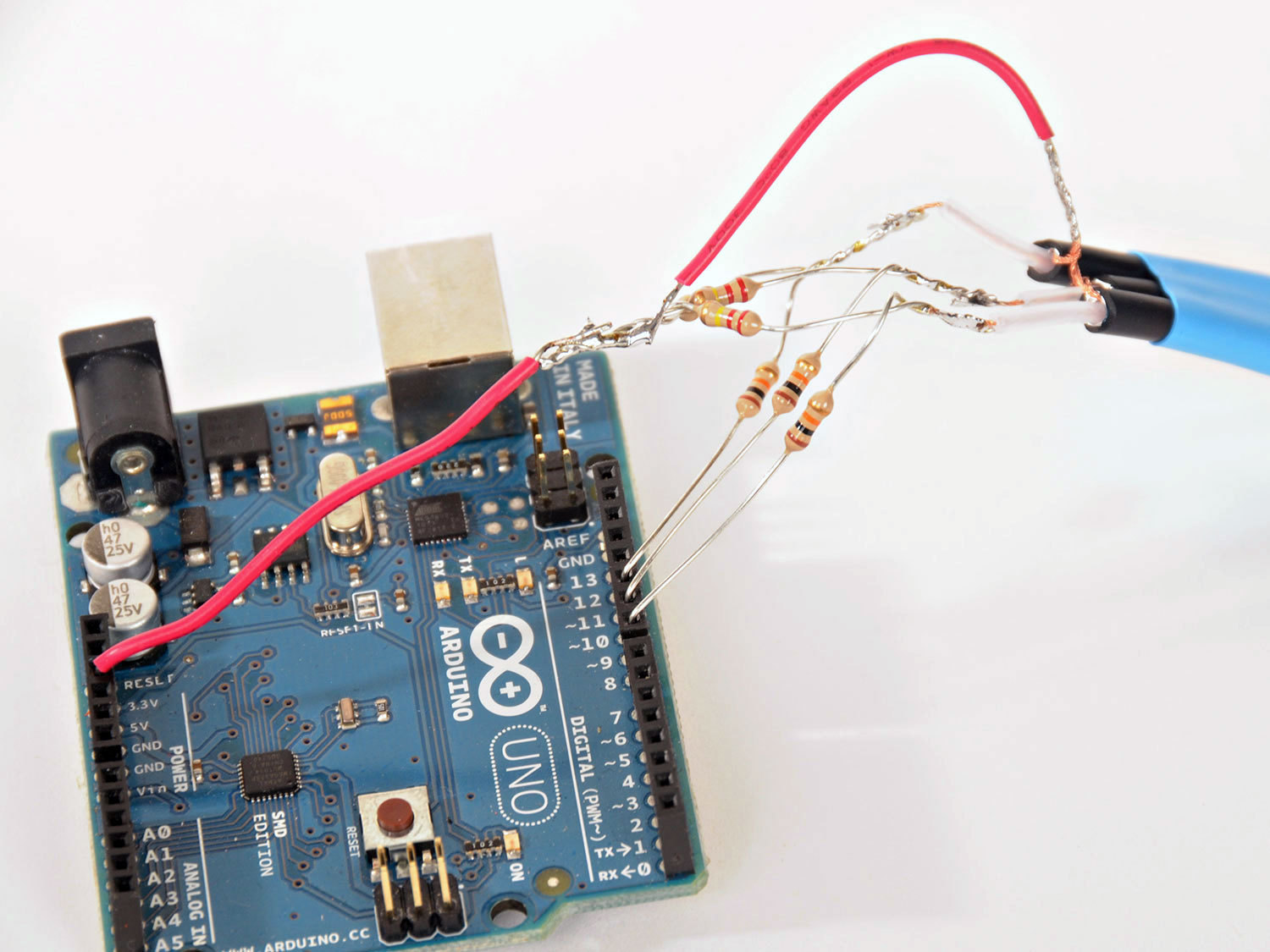
From the Arduino IDE, upload the sketch to the Arduino. Keep the USB cable connected to the Arduino, then install and load the Processing sketch.
It is important that your computer is plugged into the wall for this to work properly. If the circuit isn’t connected to earth ground (at least indirectly though your computer) you may find that your computer itself will affect the circuit.
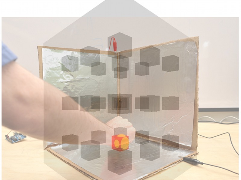
The next thing to be done is calibrate the software. With the Processing sketch running, hold down the left mouse button. Then move your hand from the far outer diagonal corner (i.e., the invisible corner of the cube closest to you) to the inner corner. Don’t touch the foil, just move your hand through the space defined by the cube. Now release the mouse button. The path your hand traveled gives the software a chance to detect the range of motion your hand will make inside the cube.
Now move your hand around inside of the cube. There should be a sphere on the screen through which you can control and move to touch all 27 cubes inside the computer model. Pressing tab will change the color of the cubes.
This is the simplest form of capacitive sensing available. In the final section, we’ll look at some alternative solutions and options to improve the system.