


As complicated as I thought this would be, this circuit is using the basic fundamentals of electronics and algebra. The only hard part is perfecting it and expanding it.
Click here to see the finished project.
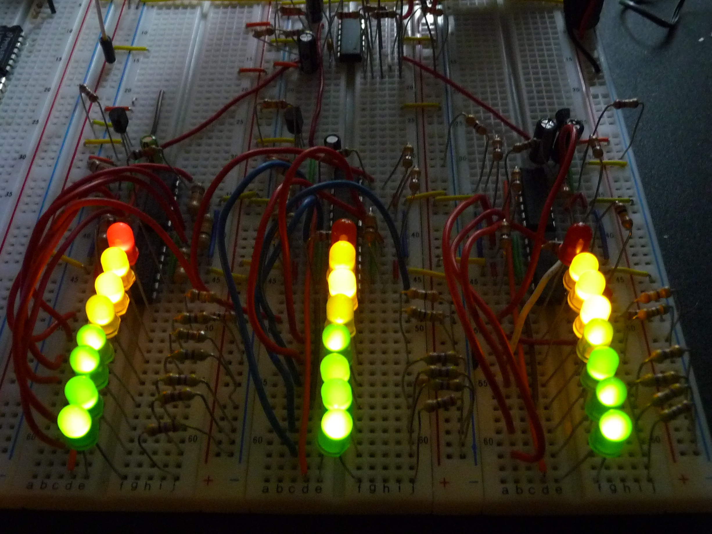
Create the bare bones of a three-channel audio-spectrum analyzer using only LM324 and LM386 ICs, and a bunch of other passive and optical components! This is a 100% analog circuit, meaning there are no LED bar-graph drivers, and no microcontroller!
As complicated as I thought this would be, this circuit is using the basic fundamentals of electronics and algebra. The only hard part is perfecting it and expanding it.
Click here to see the finished project.
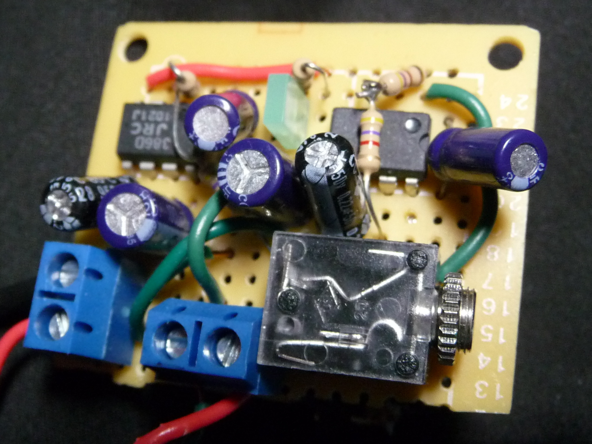
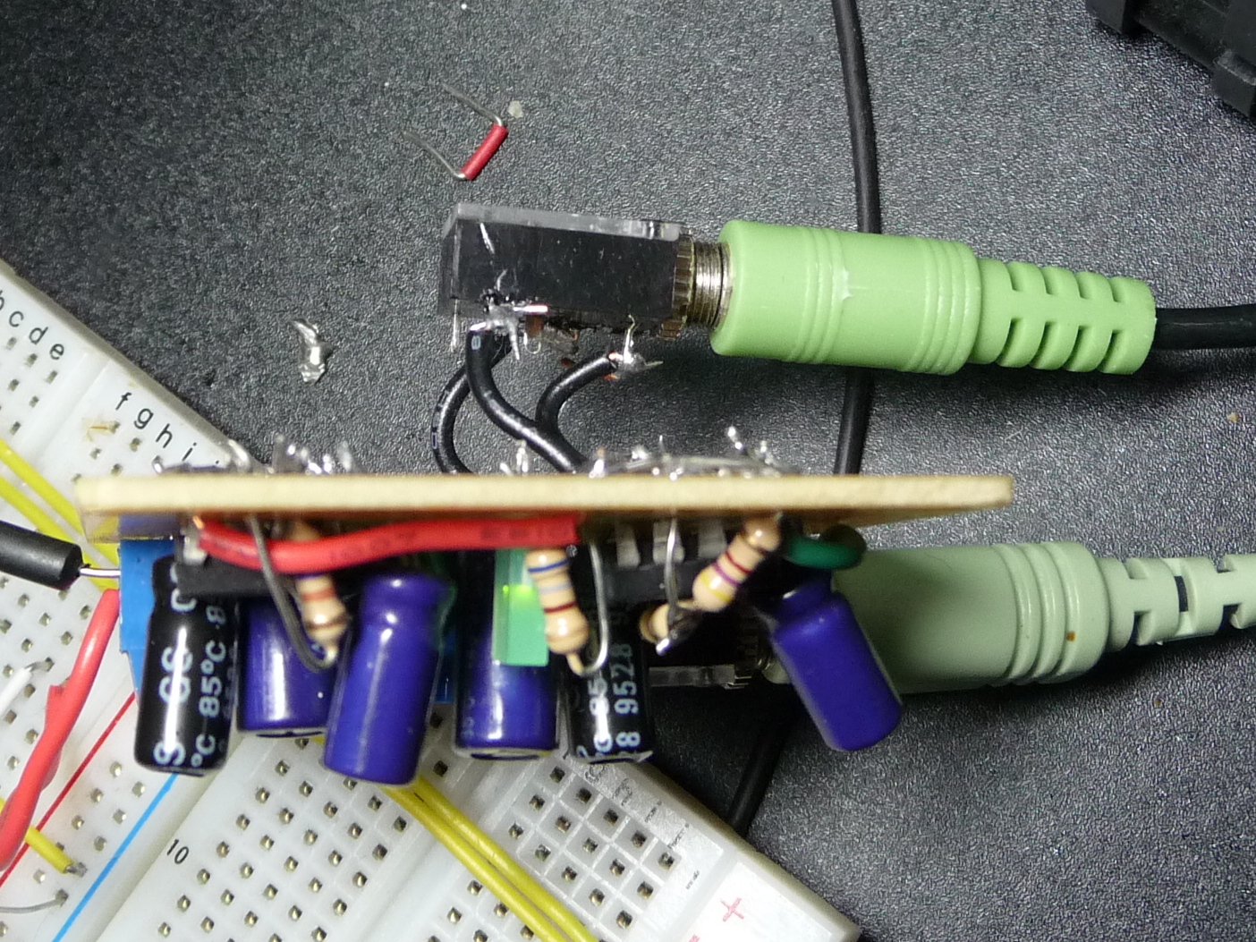
The first step of this circuit is to build a 200dB stereo amplifier. (It does not have to be stereo but it is recommended. This does not replace an audio mixer.) This also does not need to be soldered. I only did so because I would use this over and over again. So if you do plan to use it often, it is a good idea to make it permanent.
This step requires: LM386 (2/2), Green LED (1/13), Stereo Jack (2/2), Screw Terminals (2/2), .22uF capacitor (2/2), 10uF capacitor (2/3), 100uF capacitor (2/2), 470 ohm resistor (3/24), 4.7k ohm resistor (2/3).
No schematic for this part of the circuit can be given (sorry!) because my design software (LTspice) does not have the LM386 listed. (Will not work without an amplifier.) If you cannot find a schematic you will have to rely on my horrible descriptive talents in hopes of making one. To make a stereo amplifier, it is required that you make two mono-channel amplifiers (makes sense, right?) and here’s how:
Start by placing a LM386 anywhere on the board that has plenty of space. Connect pin 4 and pin 2 to V- and pin 6 to V+. Next, place a 10uF electrolytic capacitor between pin 1 and pin 8. Make sure that the cathode (- side) of the capacitor goes to pin 8. (This gives us our 200db gain.)
Next place a 470Ω resistor between V- and pin 3. Then place a 4.7kΩ resistor between pin 3 and one of the AUDIO terminals. Which one doesn’t really matter. Next, place a .22uF capacitor between pins 5 and 6. And finally place a ≥100uF capacitor between pin 5 and your output. And that should work as a mono-channel amp.
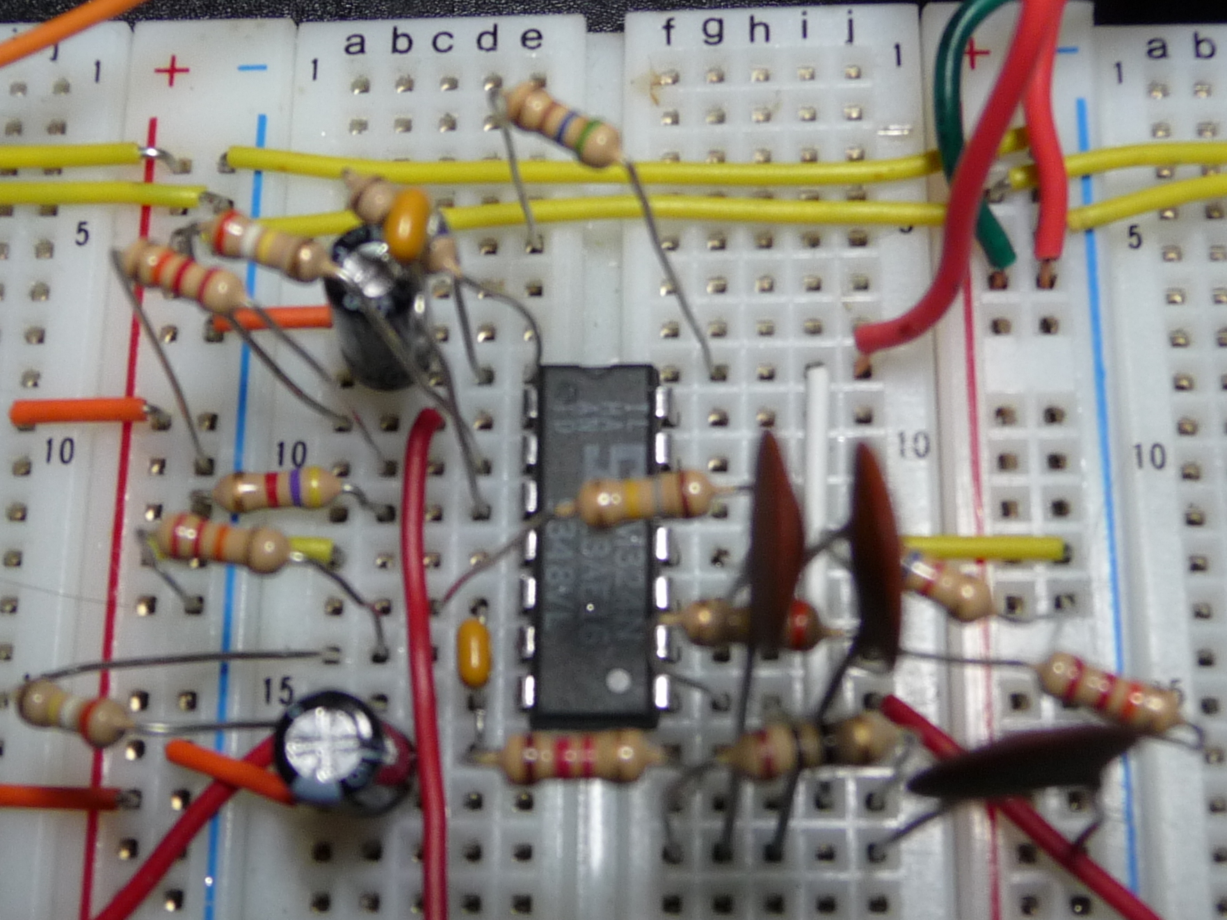
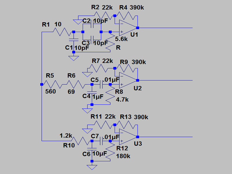
In this step we have three bandpass filters that take in the audio and we only use portions of it to create a signal and send it to the next step.
This step requires: LM324 (1/7), 10pF capacitor (3/3), .01uF capacitor (2/2), 1uF capacitor (1/1), 10uF capacitor (1/3), 10Ω resistor (1/1), 69Ω resistor (1/1), 560Ω resistor (1/1), 1.2kΩ resistor (1/1) 4.7kΩ resistor (1/3), 5.6kΩ resistor (1/1), 22kΩ resistor (3/3), 180kΩ resistor (1/1), 390kΩ resistor (3/3).
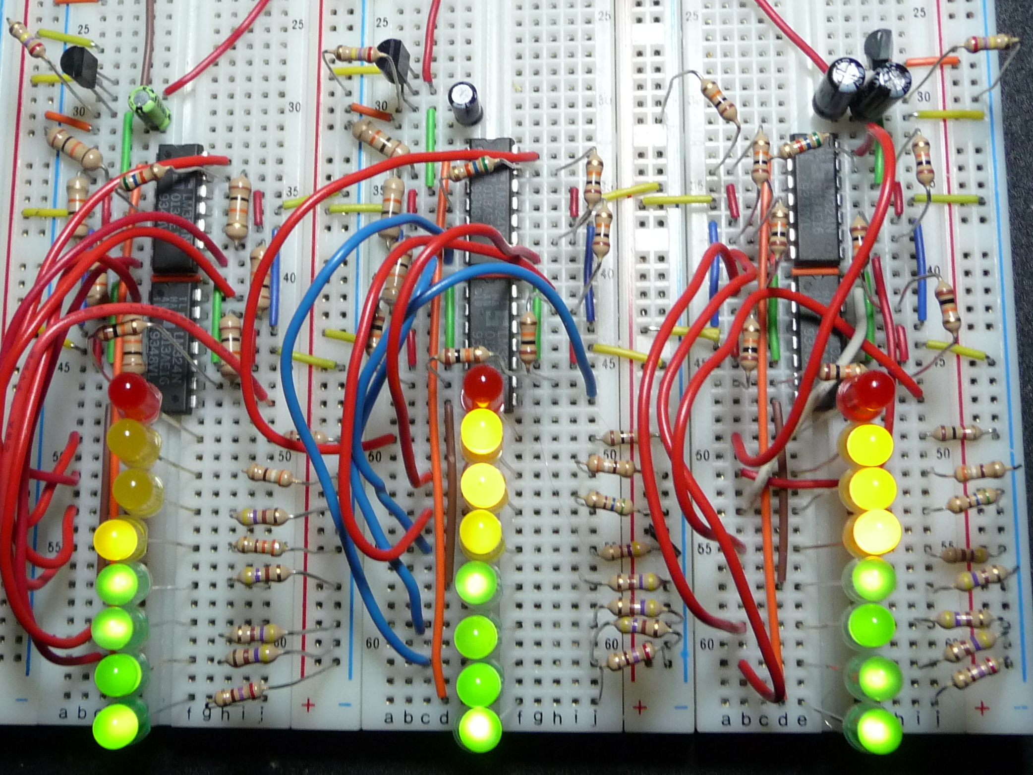
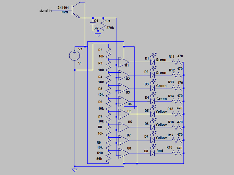
NOTE! This part of the circuit CAN be replaced by the LM3916 and the LM3916 ONLY! With that in mind, the final step is creating the display. This takes the audio and amplifies it a little more and then displays it as a bar-graph. You may need to use a wire cutter/stripper.
This step requires: LM324 (6/7), 2N4401 NPN transistor (3/3), .47uF capacitor (3/3), Green LEDs (12/13), Yellow LEDs (9/9), Red LEDs (3/3) 470Ω resistor (24/24), 1kΩ resistor (3/3), 10kΩ resistor (24/24), 56kΩ resistor (3/3), 270kΩ resistor (3/3).
The schematic given is for only 1/3 of the display. It will need to be made three times. Also, this circuit was designed to run on 5V. Increasing the voltage would require you to change things around a bit. Use only 5V to get the same end results I have gotten.
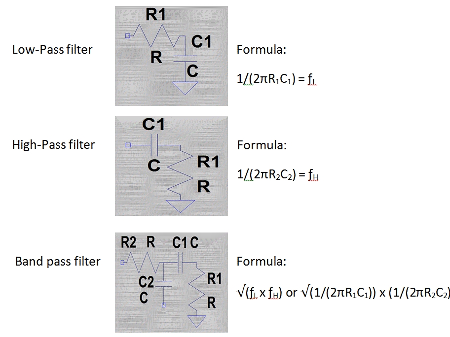
These are formulas to change values or extend the circuit. You can use these to create more bands and choose what values to use! Make sure you use a calculator!
Every part on the parts list is a part on my circuit board. If you change something, something bad (or good) might happen. Working with op-amp band-pass filters, a slight change in the values given will throw off the results. HOWEVER: You may not end up using all the parts (e.g., screw terminals) because you may not solder your LM386 set on a board. I only included them because I did solder them. And they are used for power and signal out. But other than that, nothing should be unused or traded out. You might also not use the second audio jack. It is not mandatory, but it would be silly if you can't hear the music/sound with your new spectrum analyzer. The second jack allows you to plug in your speakers while they are disconnected by the first jack.


