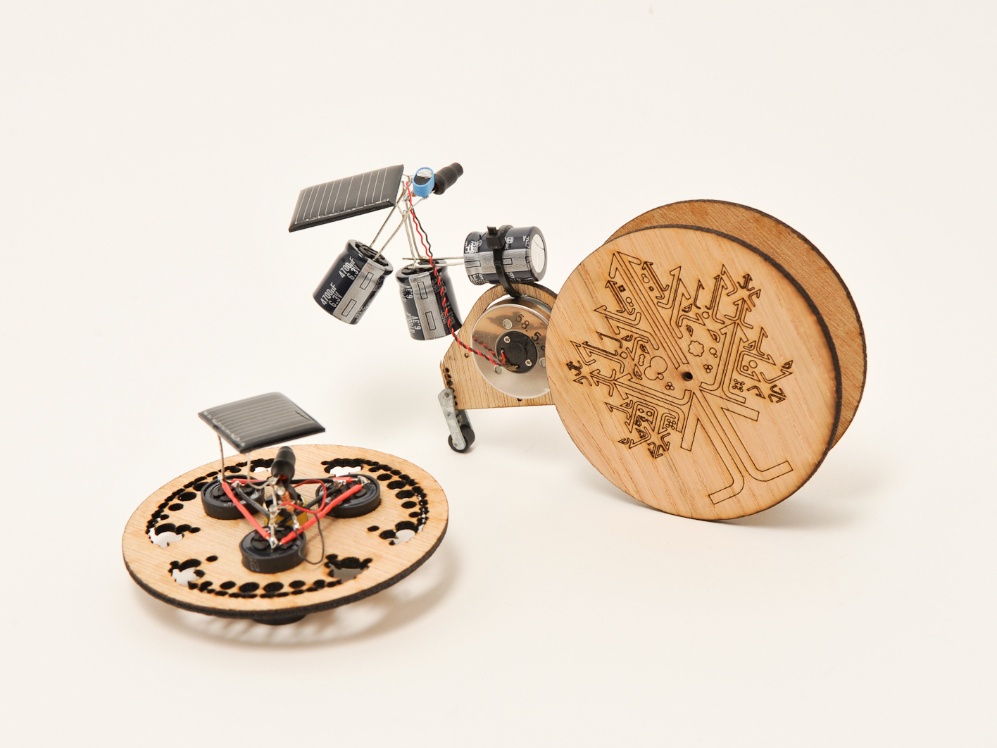
BEAM robot building techniques allow you to build fun and simple little robots with lots of room for stylizing. BEAM robots can move anywhere from a fraction of an inch to a couple of feet, depending on how big their capacitors are. You can also use batteries. For these two projects, we’ll use what’s known as a "solar engine" (Type 1 "FLED" variety), some store-bought and scavenged electronics, and laser-cut and gold-leafed wheels to build some stylin’ little Solar Chariots. Let the build begin!
BEAM is a type of robot design that allows you to create little robot/robot-like critters and vehicles mainly using basic analog components (resistors, transistors, capacitors, diodes, LEDs). The challenge is to try and get as much robot-like behavior using these components. BEAM is an acronym for "Biology, Electronics, Aesthetics, Mechanics" and these four elements serve as inspiration in all BEAM design. You can find our more about BEAM on our BEAM robot page. You can find out more information on the FLED-type solar engine of the BEAM Wiki.
Cover the LED with some heat shrink tubing, tape, or opaque paint.
We're not actually using the LED as a light, we're using it as a conductor that will trigger the discharge phase of circuit.
To shrink the tubing, if you don't have a heat-gun, you can use the tip of a soldering iron or a lighter. Hold the heat-source closer and closer to the tubing until it starts to shrink.
Be careful with your heat source and close in slowly until the material starts to shrink. Don't melt it or set it (or you!) on fire.
Solder on the LED. Make sure the negative lead (shorter leg) connects to the negative wire of the solar panel. Make sure the positive lead connects to the center lead on the 3906.
Solder on the 2.2KΩ resistor as indicated in the illustration. Unlike the LED, it is not polarity sensitive and it doesn't matter what direction the resistor faces.
Solder on the three 4700uF capacitors, in parallel, hooking them up to the positive and negative leads as show in the diagram (only one is depicted in the image for simplicity's sake).
Solder on the motor, as shown in the diagram.
Congratulate yourself. You now have a FLED-based BEAM solar engine built.
This solar engine is called a FLED-type, which stands for "Flashing LED." When the circuit has charged up enough to flash the LED, it acts as a conductor which allows electricity to flow through it and trigger the discharge phase of the circuit, sending precious power to our chariots.
If your LED is blinking, try raising your resistor value. Try within the 1KΩ to 10KΩ range (we started with a 2.2KΩ resistor).
Different color LEDs require different amounts of voltage. From lowest to highest: Red, Green, Blue, White.
If you hear a high pitched pulsing a lot of times, the easiest fix is finding a more efficient motor. That sound means the motor isn't getting enough power to turn over.
Only very efficient motors work well in this circuit. Try hooking up your motor to the circuit/cell and feel the amount of torque it's delivering to the motor shaft. If it feels strong (an educated guess), then you can try hooking it up to the chariot.
If you haven't already done so, download the Chariot Racers template here.
The Symet template has a 0.428" hole in the center for a motor and three 0.637" holes for capacitors. Cut to fit your parts. The rest of the holes we added for decoration.
If you have capacitors that are larger than the holes in the template, you'll have to enlarge them.
The rest of the structural components will be used to make our solar roller.
The first Chariot we'll build is called a Symet in BEAM parlance ("sym" for symmetrical). Symets are little BEAM tops that store the sun's charge in capacitors and then dissipate it for a spin.
The Symet balances on a DC motor's axle which spins to make our top move.
Parts can get heavy in a hurry. Make sure you've got the right mix of enough voltage from your flashing LED and power required to turn your salvaged motor over.
If your LED is flashing you might need a larger resistor.
If nothing happens, check all of your connections. These little guys can be fragile.
Now let's use the same type of solar engine to build a type of BEAM vehicle known as a solar roller.
For this solar roller chariot, we've salvaged extra parts from an old microcassette player to drive our bot. We'll use the same configuration of three 4700uF capacitors as our power source.
For our solar roller, we harvested a wheel, motor, pulley, belt, and screws from the guts of a microcassette player.
You can use the same laser-cut and gold leaf treatment on the roller wheels.
Don't forget: One aspect of the BEAM ethos is "Aesthetics." This offers an opportunity to really get creative and make something that looks really cool and expresses your creativity.
BEAM robots also frequently make use of scavenged parts. Many BEAMbots are made entirely of techno-junk. In the past, we've used old hard drives' disks, cardboard, or cut-up plastic jugs for roller wheels.
Connect a motor to the rear of the main body component for the chariot. There are two different body templates. One allows for a 1.2" motor to be pushed through (shown here). The other allows for a pancake motor to be attached.
Put a 0.3" long piece of 1/8" metal tubing in one of the eight holes (seen to the left in the image) on the body component, appropriate to the length of your drive belt. Use super glue and heat shrink tubing to keep the tube in place. The axle for our two large chariot wheels will go through here.
Use screws taken from the cassette player to secure the motor to the body.
A roller wheel harvested from the cassette plater serves as a back wheel.
A small C-clip holds the rod of the wheel assembly in place. You can use pliers to carefully push the rod out, thus pushing off the C-clip in the process.
The rod is then press-fitted though a hole of your choosing on the body.
Laser-cut out the wheels (found in the template in Step 4). Use a lower power setting when cutting the design so as not to cut though the wheels. Flip the wheels over and engrave spots for where to glue the wheel extenders. Note: You will have to freeze and unfreeze layers in the drawing files to keep parts aligned.
Glue the wheel extenders onto the wheels. Two extenders go on each side of the wheels.
Glue the brass pulley from your cassette player onto the wheel extender with the larger hole.
Glue a 0.62" length of the smaller hollow tubing over the axle of the pulley. This will be the axle that the other wheel will be attached to after the wheels are on the body component.
Make sure the wheel with the belt pulley lines up with the motor.
Some oil in the spacer tube helps the wheels turn more freely.
Put one wheel in and connect the other side with some glue. The wheels should easily rotate in the spacer tube.
Attach the FLED circuit to the body with a zip tie, then solder the motor wires to it.
Attach the solar cell simply by soldering it onto your solar engine circuit, making sure positive and negative are correct as per the illustration in Step 3.
As you can see from the images, we just used the leads from the transistors to provide the structural connection to the chariot. Besides making it easy, it also allows you to adjust the angle of your cell for maximum light exposure.
Step #17: You\'re Off to the Races!
Now you're ready to put your BEAM Chariots into some bright sunlight (or artificial light) and watch them charge up and activate. Make more than one of each type and have a race.
For the Solar Roller, once you've made and tested one, you can try making more and tweaking the design to cut down on weight, reduce friction, use a larger capacitor to store more power (if you used a capacitor) and other improvements. You can learn a lot by this trial-and-error process.
Hey Tony,
The reason we list two 2n3904 Transistors is because there are two builds in this Make: Project, and each project requires one. I also see both the 2n3906 and 2n3904 listed in item list, but the video is incorrect. It should list a 2n3904 and 2n3906 for each build, and thanks for keeping an eye out.
There’s a treasure trove of solar engine circuits (including FLED) available at:
http://costaricabeam.solarbotics.net/Circuits/SolarEngines_Main.htm
// What's Trending
Raspberry Pi Design Contest
Seventeen Sneaky Secret Hides
Teardrop Camper Trailer
10 Things to Connect to Your Raspberry Pi
Lost PLA Casting from 3D Prints
DIY 3D Laser Scanner Using Arduino
I Have a (Puzzling) Dream
New Project: DIY 3D Laser Scanner Using Arduino
// What's Shared
A better way to slice a pumpkin
DIY Nerf Darts
100 Dollar Store Organization Ideas for Craft Rooms and Beyond
In the Maker Shed: Minty Boost USB Charger
Mad’s Mouse House
Lace Princess Crowns
I Have a (Puzzling) Dream
Play the Rings of a Tree Trunk Like a Record
// Most Commented
DIY Hacks & How To’s: Get Emergency Power from a Phone Line
Resin Casting: Going from CAD to Engineering-Grade Plastic Parts
Ten Tips for Screws and Screwdrivers
Ten Tips for Better Measurement
Is it a Hackerspace, Makerspace, TechShop, or FabLab?
Makers on TV: Big Brain Theory
Arduino Announces New Wireless Linux Board
Grow: A Portable CNC Router System