


I am going to guide you through the process of making a circuit that will allow you to control a servo by turning a dial. At the same time I will explain what is going on in the circuit and how it works.
Projects from Make: Magazine
Control a Servo Motor Without Programming
This guide will show you how to make a simple circuit that is capable of controlling a servo motor without using a programmable chip.
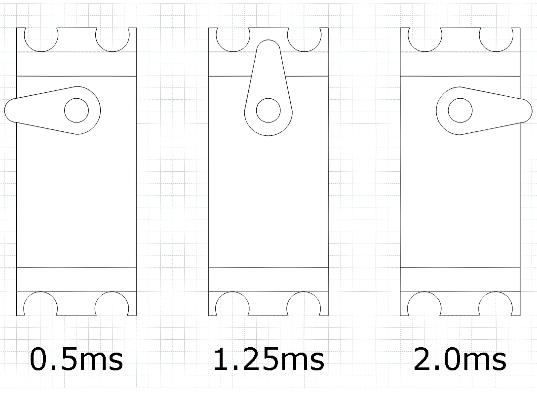
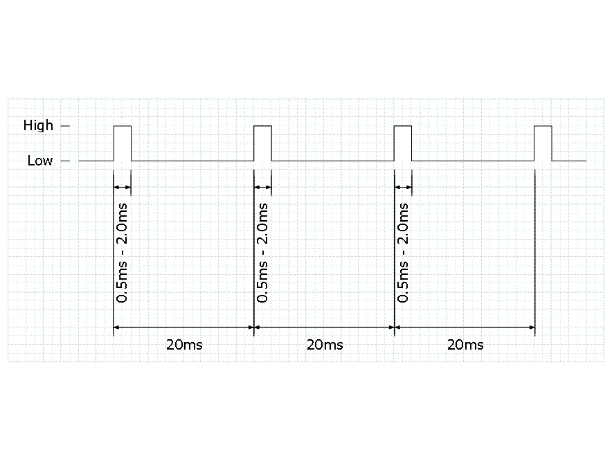
A servo motor is controlled by sending a series of pulses to it. This is called “pulse width modulation.” Depending on the length of the pulse it will turn to a specific angle.
A pulse must be sent to the servo every 20 milliseconds. The pulse length will vary from 0.5ms to 2ms. If it is 0.5ms the servo will turn as far as it can anti-clockwise. If it is 2ms it will turn as far as it can clockwise.
By using a pulse-generating circuit controlled by a potentiometer any pulse length between 0.5ms and 2.0ms can be sent to the servo. This allows us to move the servo arm to any position desired.


To create these pulses we are going to use a 555 timer circuit.
There are two types of 555 timer circuits, astable and monostable. For this project we will be using an astable circuit. This means that it will continually send pulses as long as it has power.
The circuit uses a 555 timer chip, with capacitors and resistors controlling the timing. For this circuit we will be using the NE555.

This is the circuit diagram for the servo controller. You can either make it on a PCB, on veroboard, or on a breadboard.
Whichever you choose you should always breadboard it first. This lets you check that you have all the right components and the correct layout.


This is my circuit that I made. I made it on veroboard and everything is working fine.
A few tips to remember when using veroboard.
1st; always drill through the track where your chip is BEFORE doing any soldering.
2nd; always use a dill / chip mount to hold your chip. This prevents the chip from getting damaged when soldering.
3rd; always pass leads through the board before soldering them in. This prevents them from getting damaged if pulled upon.


