Make: Projects
Geiger Counter
This radiation detector clicks, flashes, logs radioactivity levels, and shares its data with the world.
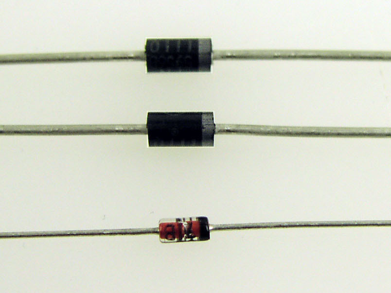
I’ve been designing, making, and selling Geiger counters for 15 years through my company, Images Scientific Instruments. They’re fundamentally simple devices; you just need voltage high enough to run the Geiger-Müller (GM) tube. Anyone can design a counter that will work somewhat, but it’s hard to make one that’s reliable and long-lasting, because the electronics are so touchy.
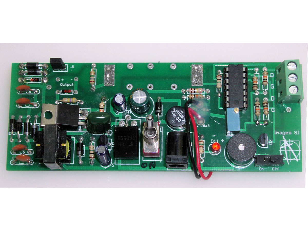
Last year I was redesigning my basic Geiger counter circuit when the earthquake, tsunami, and nuclear crisis hit Japan. We sold out immediately, and I was so swamped with orders that I had to put my improved design on hold. But I finally finished, and here it is.
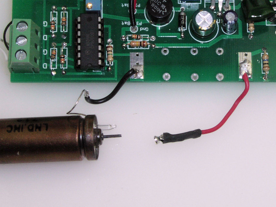
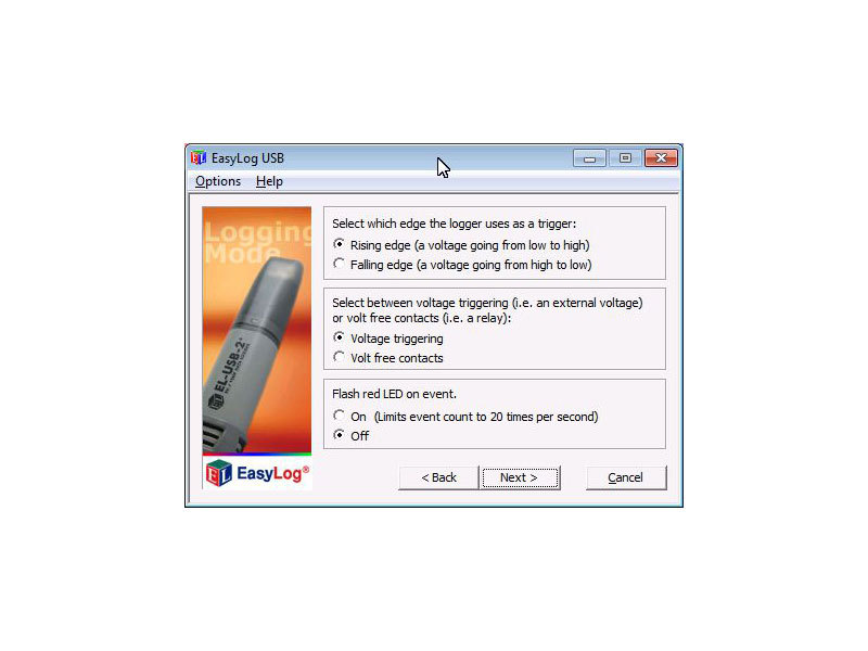
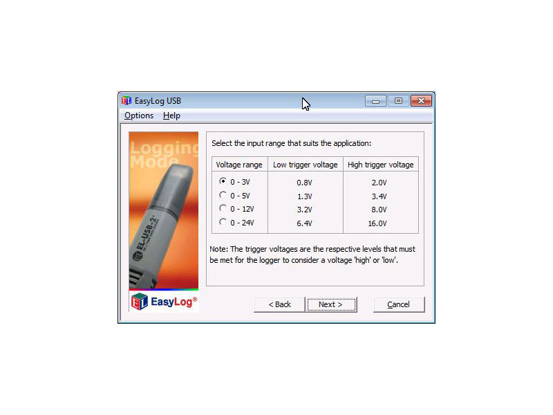
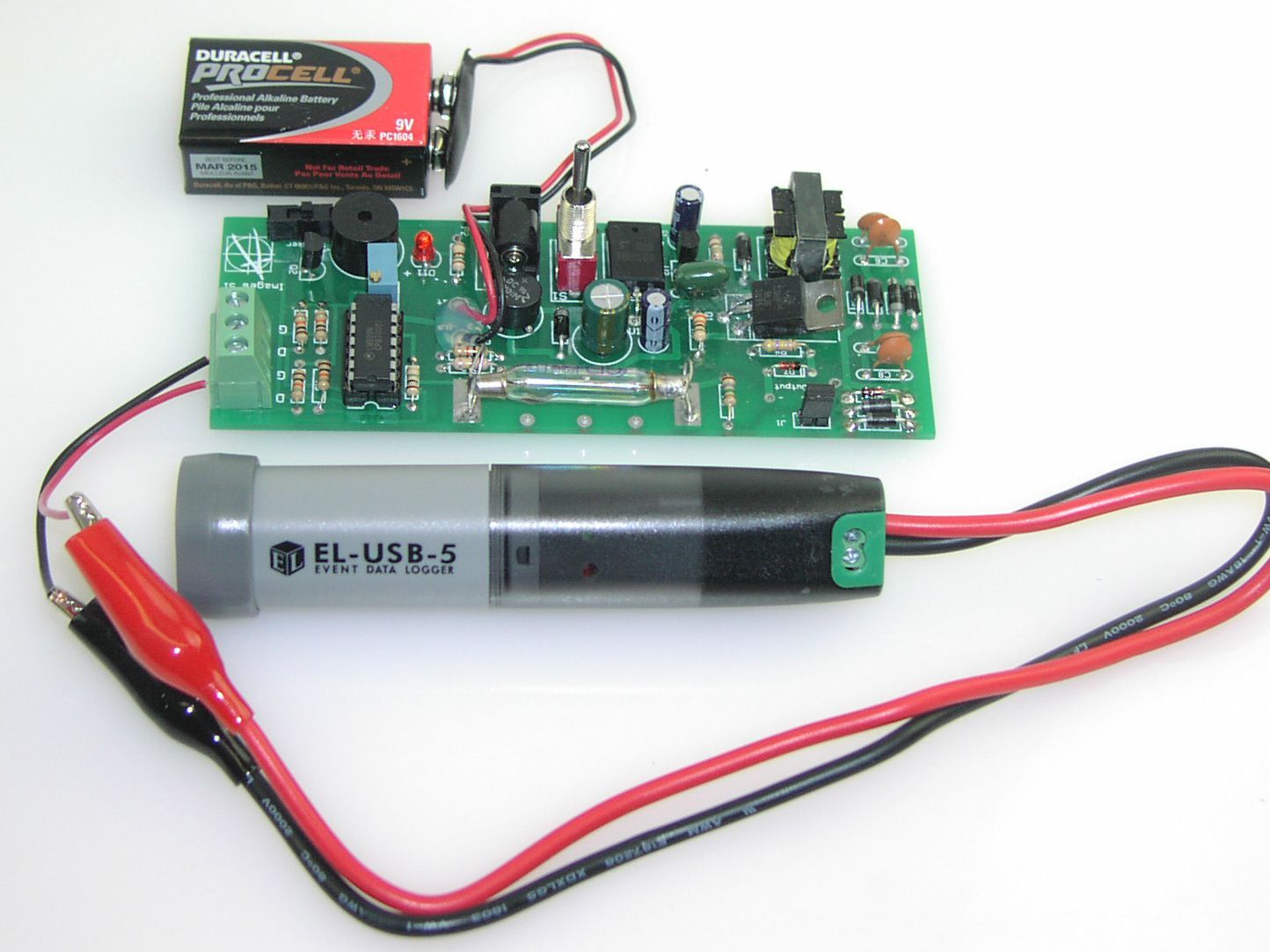
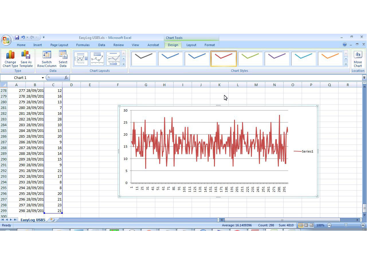
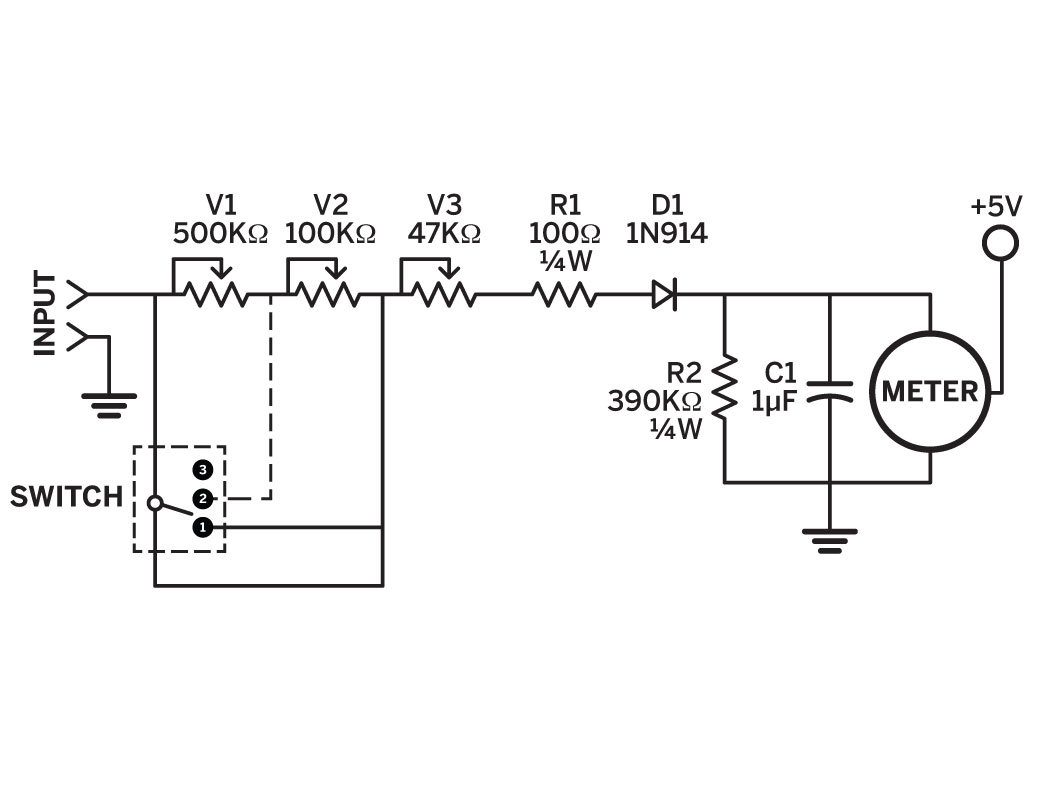
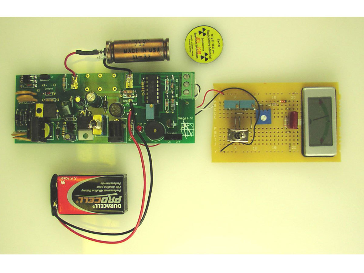
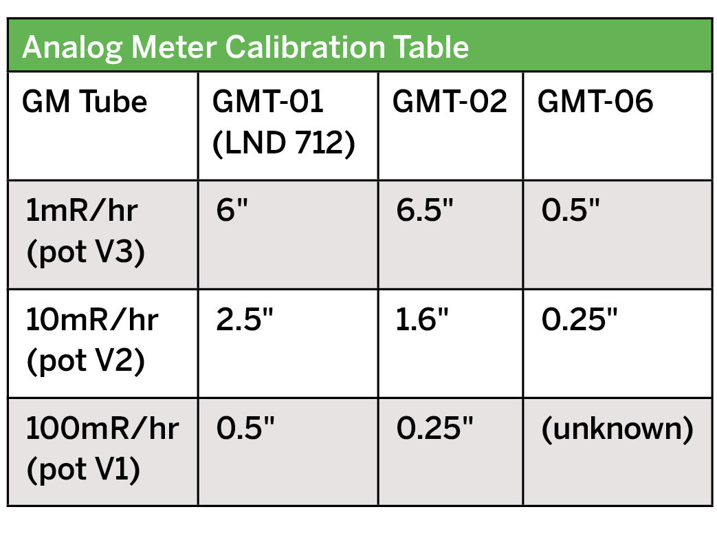
You can easily configure this counter to use a variety of GM tubes. Not only will it output a click and an LED flash with each radioactive particle detected, you can also connect it to analog or digital radiation-level meters, a PC for plotting data, a portable SD-card data logger for placing somewhere without a computer, and a true random number generator. It’s also compatible with the Radiation Network (http://radiationnetwork.com), so you can share your readings with others worldwide.
Steps
Step #1: Assemble the PCB.
Next


- From your GM tube’s specifications, note the voltage required to drive it. This should be an even hundred number between 300 and 600 volts. Match this number by totaling the values of up to three 100V or 200V Zener diodes; for example, use two 200V Zeners and one 100V for a 500V tube.
- Solder the Zeners into positions D8–10 on the circuit board, following correct polarity. Fill D8 with a 100V Zener, if used. Nearby jumper J1 bypasses D8, which lets you quickly adjust the tube voltage down 100V.
- Find the values for anode and cathode resistors R5 and R4 by referring to the specifications for your GM tube.
- For the tubes I stock, the recommended anode resistor value ranges between 2.2MΩ and 10MΩ. The LND 712 tube shown in Step 2a needs a 10MΩ anode resistor and a 470KΩ cathode resistor. Solder resistors R5 and R4 where indicated on the PCB.
- Follow the silk-screened labels on the PCB (or the schematic diagram at http://makeprojects.com/v/29 if you’re breadboarding) to place and solder all remaining components to the PCB. Be sure to orient all components with the proper polarity.
Conclusion
The Hidden Landscape of Radioactivity
Test for Radioactive Contamination
If you’re testing for contamination, your GM tube should be sensitive to alpha radiation as well as beta and gamma (like the GMT-01).
Geiger counters can only test for gross levels of contamination that show up clearly above background radiation; they are not the proper instruments for detecting low-level contamination. That said, here is how to test for radioactive levels above background:
- Establish the background radiation level by measuring CPM for at least 20 minutes, and longer is better. Note the lowest and highest levels and then average them all to establish the baseline minimum, maximum, and average. With my data from Step 4, a 298-minute sample, my average CPM was 16, and min to max was 6 to 28.
- Position the GM tube very close to the top surface of the material you’re testing, and run the counter, recording the CPM output. The longer the run, the more accurate the results.
- Compare the radiation output of your sample against your baseline.
Alternative Sound Output
If you want louder clicks from your Geiger counter, you can use the alternative sound output circuit; see the schematic at http://makeprojects.com/v/29. In this circuit, the pulse signal from the comparator triggers a 555 timer chip, which is set up in monostable mode to stretch out the pulse it receives on its trigger. The output pulse from the timer flashes the LED and outputs an audible click to the speaker via pin 3.
The alternative circuit’s components (555 chip, caps, resistors) fit on a small breadboard. You can connect it to one of the main board’s digital outputs, or to where the standard light and sound output connects (LM339 pin 14), either replacing the original output or making it switchable.
Digital Meter Adapter
You can do more with your Geiger counter by wiring its digital output to a standard 3.5mm mono earphone jack, connecting ground to the sleeve contact and signal to the tip.
This output jack lets you connect the meter to my company’s Digital Meter Adapter (DMAD) an add-on that shows CPM or counts per second (CPS) along with milliroentgens per hour (mR/hr). Onboard switches also configure the adapter to work as a true random number generator, with multiple ranges. The DMAD (see inset, opposite) has a second 3.5mm plug for output, which lets you connect any of its output functions to a computer via 3.5mm to RS-232 serial cable.
Radiation Network
Want to help keep track of radiation levels nationwide? A 3.5mm output jack, as connected to the Digital Meter Adapter above, will also let your Geiger counter become a monitoring station for the Radiation Network (http://radiationnetwork.com), home of the National Radiation Map. The network software is sold with an adapter cable ($79 together).
For schematics and a template for an acrylic enclosure, see http://makeprojects.com/v/29.
Caution: The Author and Publisher do not make any warranties (express or implied) about the radiation information pro-vided here for your use. All information provided should be considered experimental. Safety and health issues and concerns involving radioactive contamination should be addressed, confirmed, and verified with local and national government organizations or recognized experts in this field.
This project first appeared in MAKE Volume 29, pages 100-111.


