Make: Projects
Infrared String Bass
We take Len Keeler's elastic string bass to the next level, adding multiple strings that use IR transmitter/detector pairs to create an optical pickup system.
In this project we’re going to take inspiration from Len Keeler’s original Elastic String Bass. We’ll pick it up (no pun intended) and run with it, adding multiple strings for different tonal qualities, etch our own printed circuit board (PCB), and of course, demonstrate the instrument.
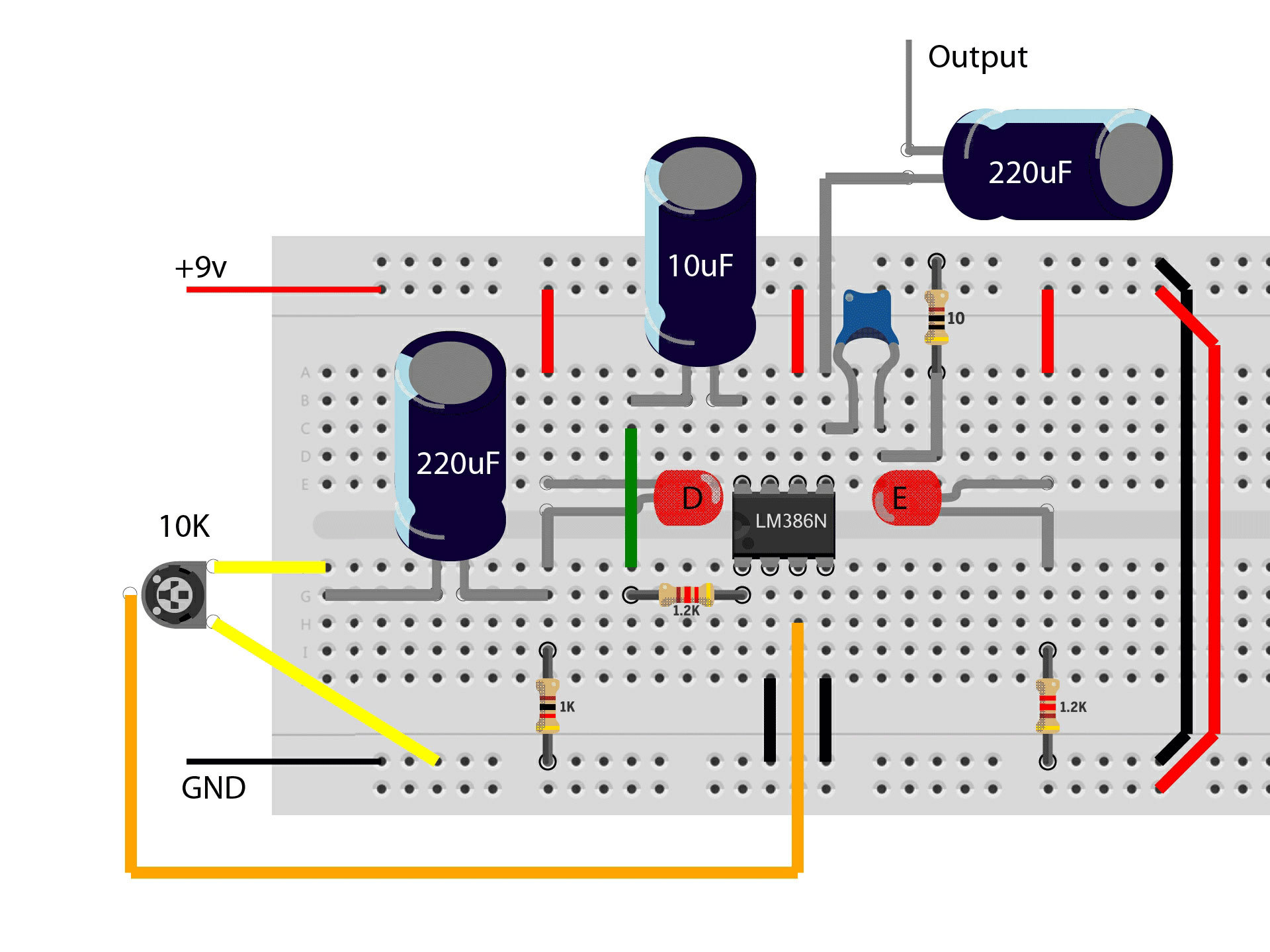
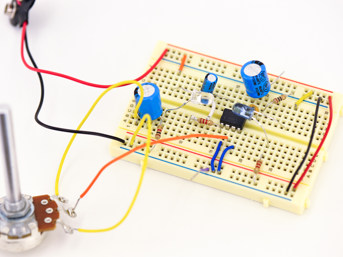
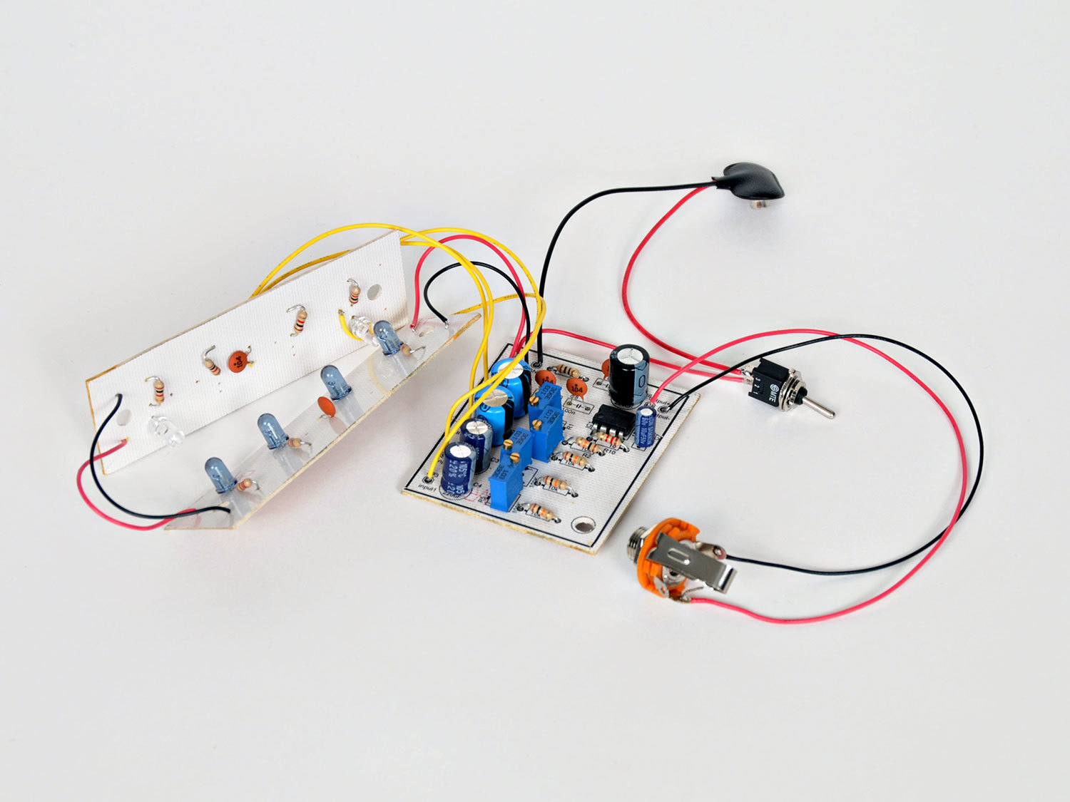
First we will breadboard the basic version of this circuit, which will introduce you to the LM386 audio amp, as well as show you how the IR emitter and detector "talk" to each other, turning interrupted infrared (IR) into audio.
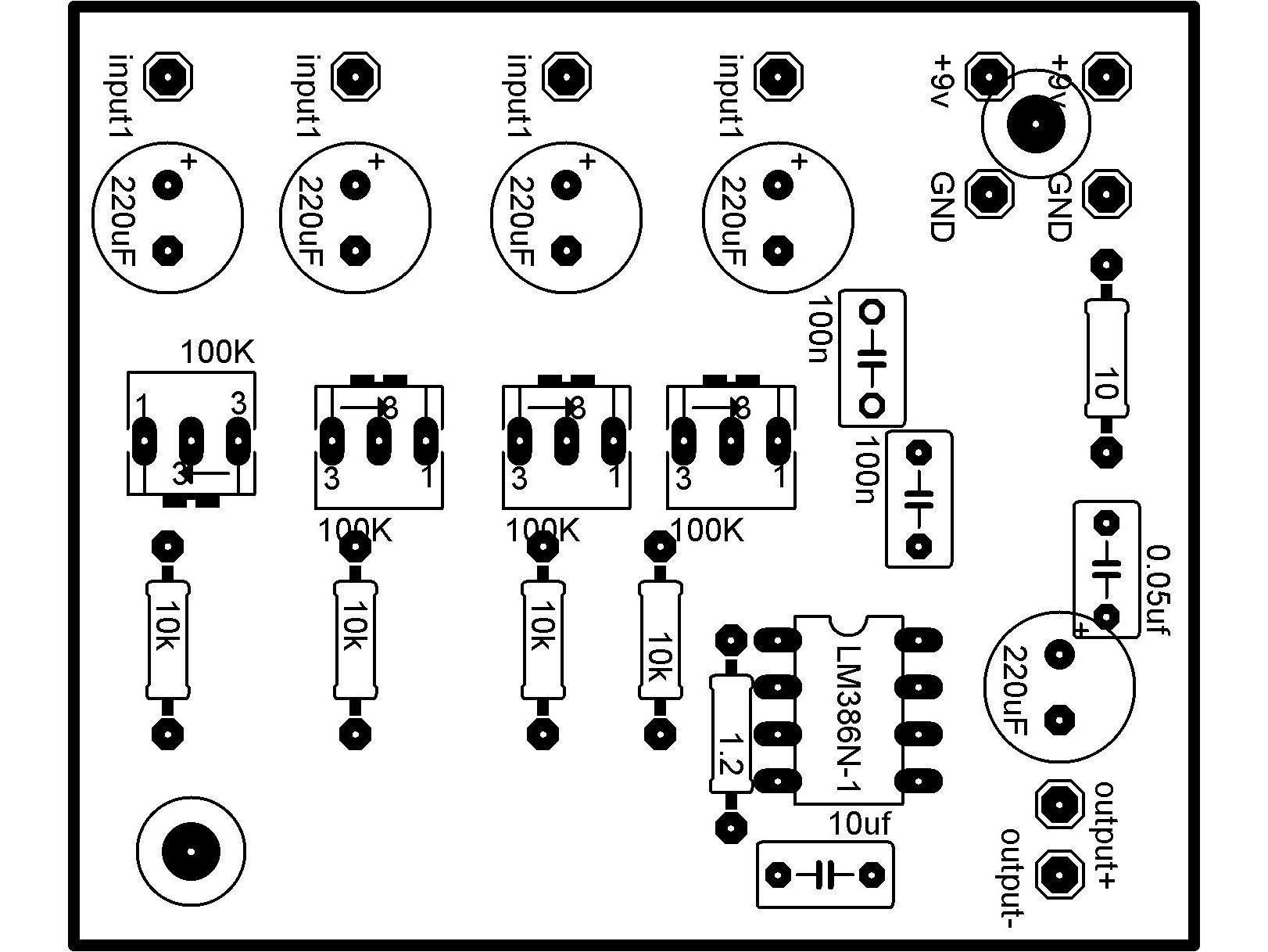
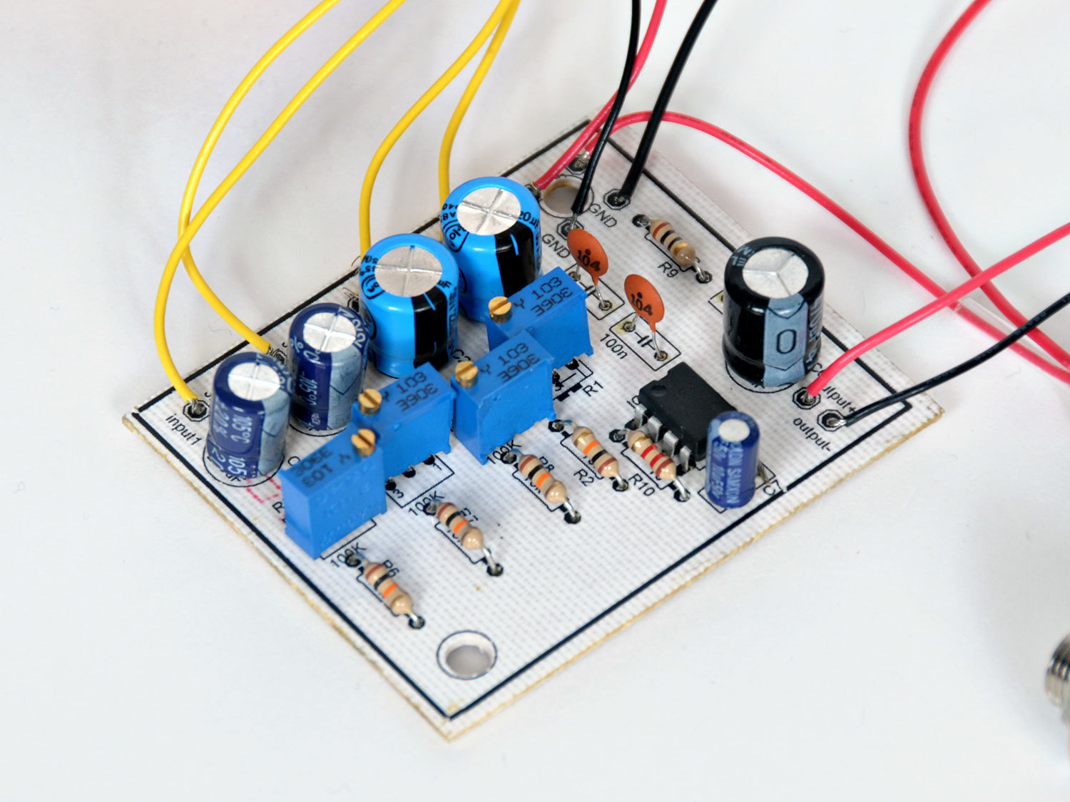
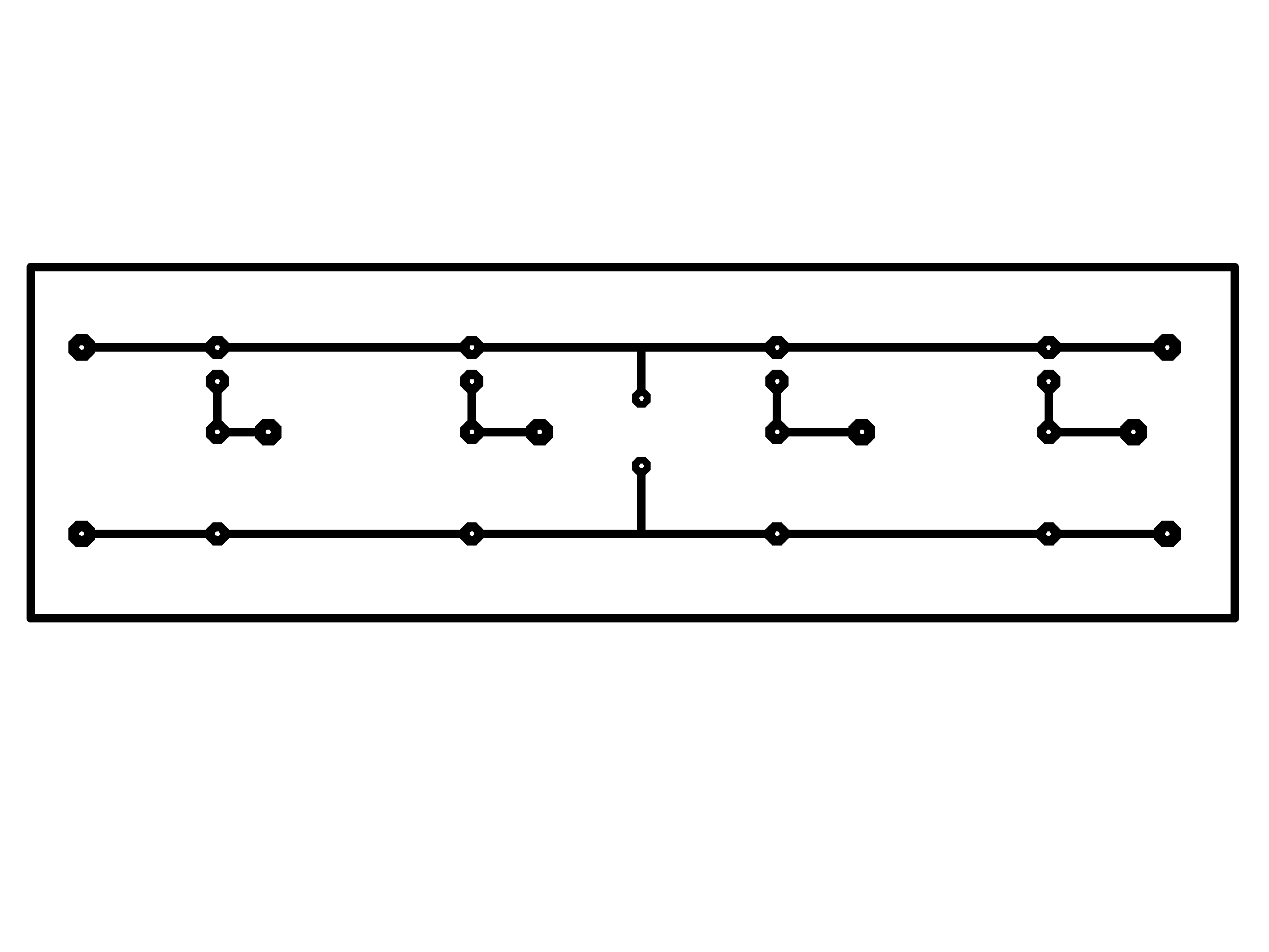
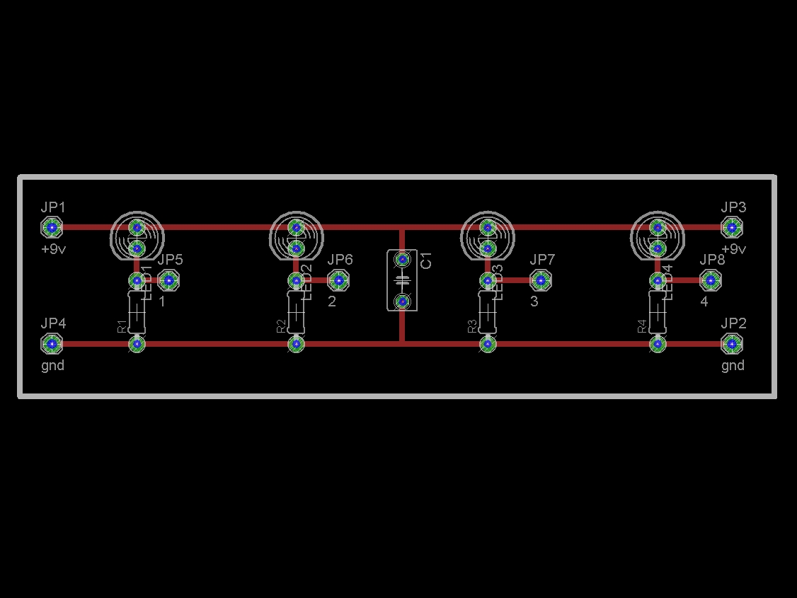
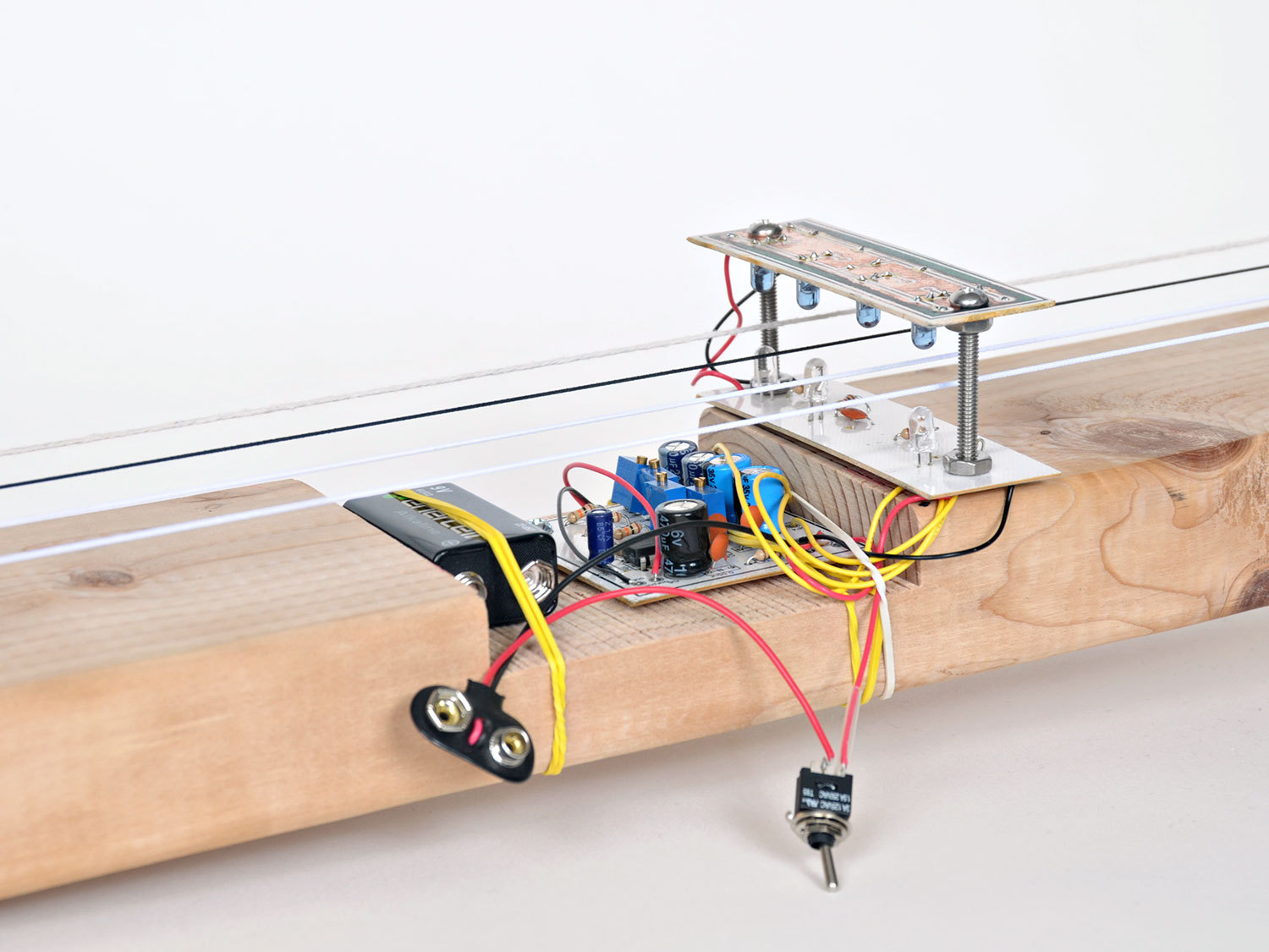
Then we’ll etch our own PCBs, including one for the main circuit, and a pair for the LED holders (acting as the guitar’s pickups).
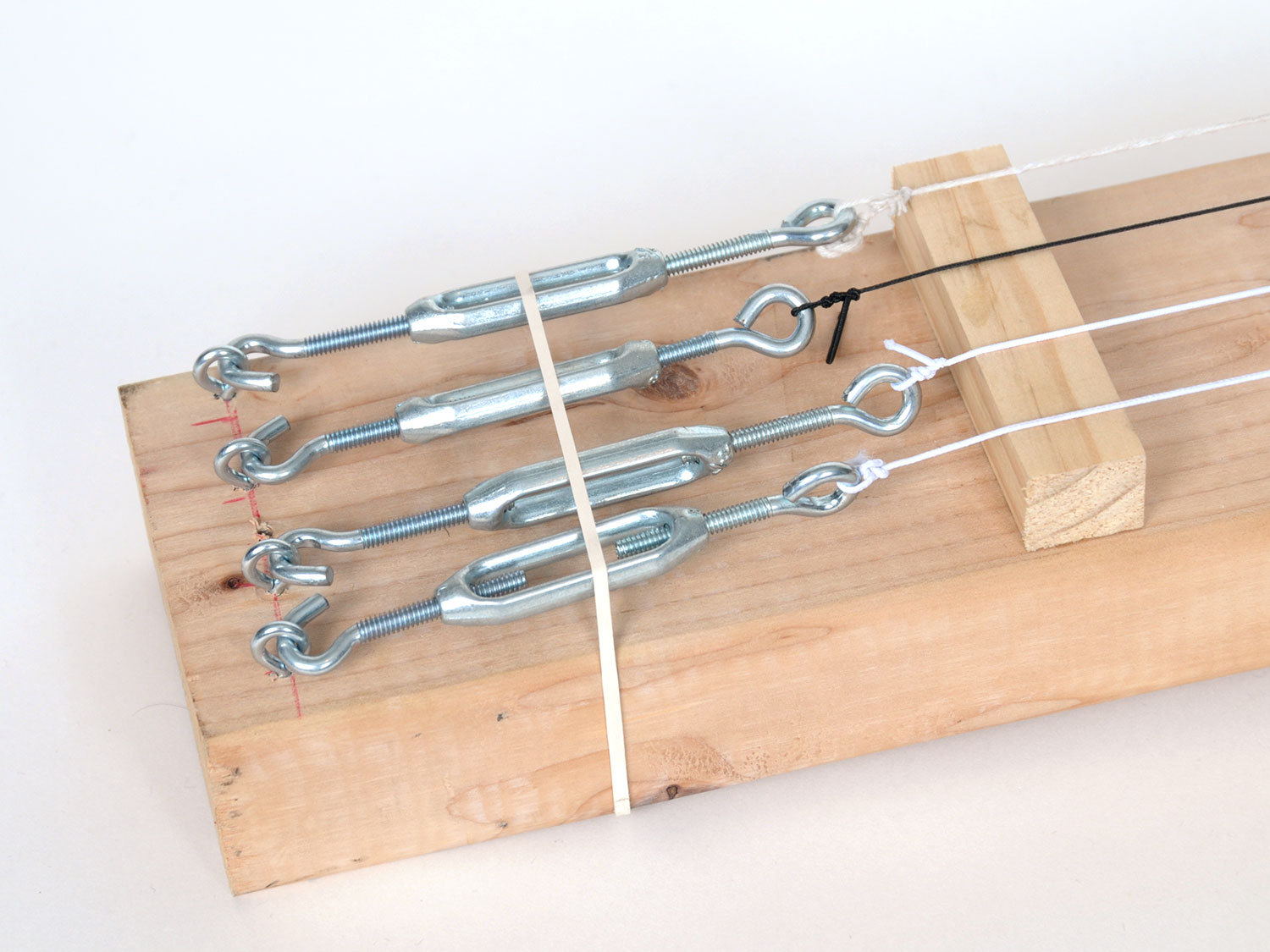
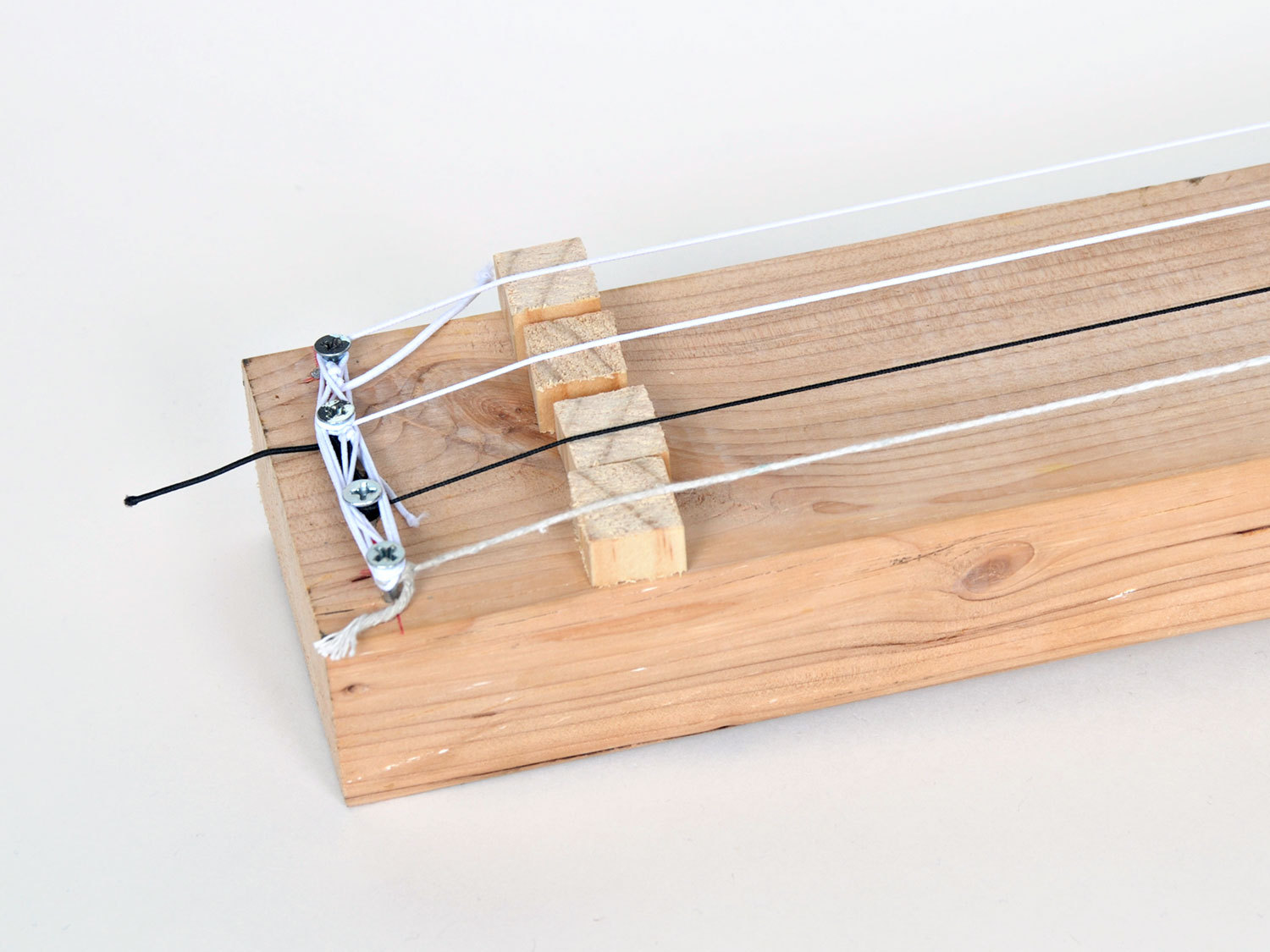
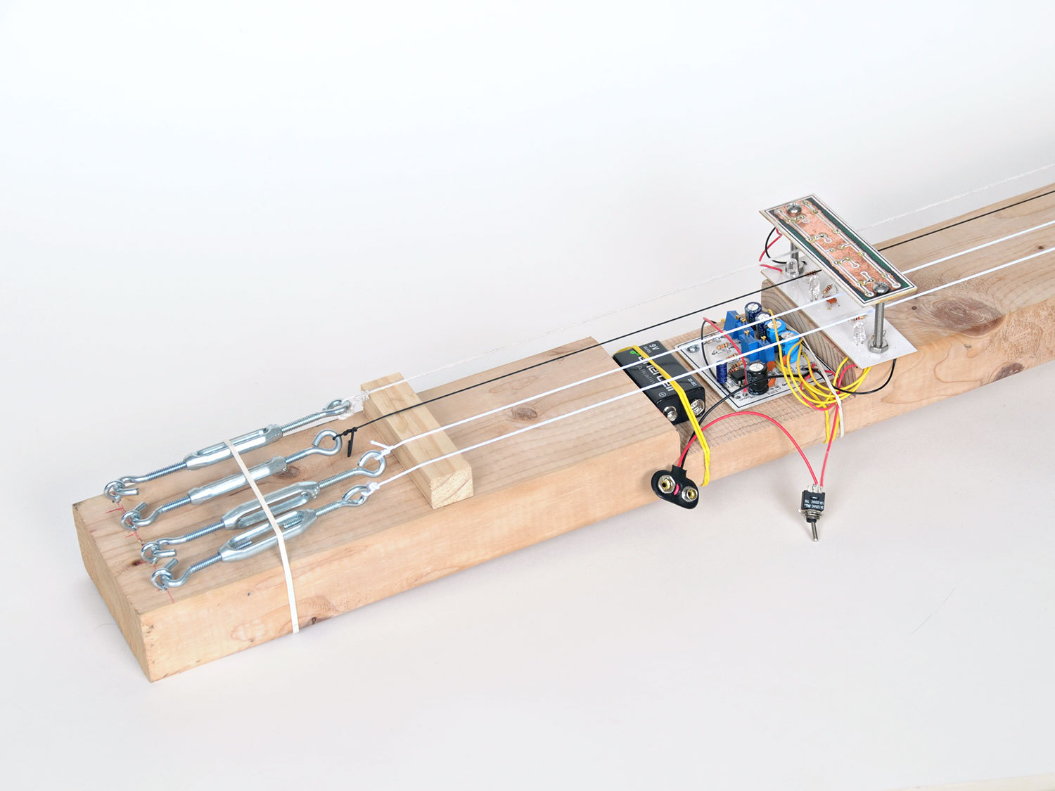
And finally, we will build a wooden body to mount everything on. I’ve used a piece of lumber, but you should feel free to modify the design with the materials you have available. Remember, unlike a traditional guitar, this circuit is sensing interrupted IR, not reverberating through the wooden body of the guitar.
Steps
Step #1: The Basic Audio Circuit
Next


- At the end of this step, we will test our breadboard circuit using an oscilloscope. If you don't have one, or access to one (befriend your local hackerspace!), simply read these points to follow along and understand how the circuit works.
- Instead of the 741 OpAmp used in the original design, we're going to use the LM386N audio amplifier. This gives us the advantage of only requiring a single 9V battery.
- We're going to use the basic circuit hookup from the LM386N datasheet and combine the IR emitter and detector driver circuits from the original Elastic String Bass project.
- Refer to the illustration and populate your breadboard with the necessary components. Note that "E" is the Emitter diode (the darker LED) and "D" is the Detector diode.
- Note : Dismiss the orientation of the "dog leg" on both LEDs in the illustration - both LEDs should have their anode (the longer leg) on top, connecting to the 9V rail. Also note the small blue capacitor in the illustration is 0.05μF.
- Bend the emitter and detector over so that they are facing each other, and hook up the 9V battery. To test this circuit with an oscilloscope, connect your probe to the cathode lead of the 220μF capacitor connected to pin 5 of the op amp, and your scope's ground clip to a piece of wire connected to the breadboard's outer rail.
- Using a rubberband stretched between the diodes, give it a good pluck. You should see a waveform generated on your scope's screen. IR light traveling from E to D is interrupted by the vibration of the rubberband, generating this waveform. If everything looks good, it's time to "up our game" & create an etched PCB to hold our circuits.
Conclusion
In this project we've taken a simple optical circuit and put it to an alternate use: detecting the "twang" in an elastic string. By marking fret positions and using the LM386 audio amp, we've reduced the battery count down to one, and made it easier to find the right notes.
What I find truly fascinating about this project is that we are directly converting an optical signal into an audio one. So not only does the type of material used to make the string affect the sound, but the color of the string does too.


Hi Drew – I can help. What OS are you on, and what image manipulation program do you use (Photoshop? GIMP?) – you only need to know the DPI if you want to make your own boards, otherwise you can send off the files and have them fabricated for you. However if you want to build it by Xmas making it yourself is the fastest – a friend and me made two sets of all the boards in one night.