


Over the years I’ve designed many electronic circuits that transform steady (DC) or modulated (AC) beams of light into sound. These circuits have many applications, some of which are described here.
Over the years I’ve designed many electronic circuits that transform steady (DC) or modulated (AC) beams of light into sound. These circuits have many applications, some of which are described here.
During my senior year at Texas A&M in 1965, I modified a simple 2-transistor oscillator by connecting it to a speaker and replacing its single resistor with a light-sensitive cadmium sulfide (CdS) photoresistor. The circuit was silent when placed at the end of my dormitory’s darkened 200-foot hallway. When a fellow student struck a match at the far end of the hall, the circuit emitted a loud buzz that amazed me as much as the students who were watching.
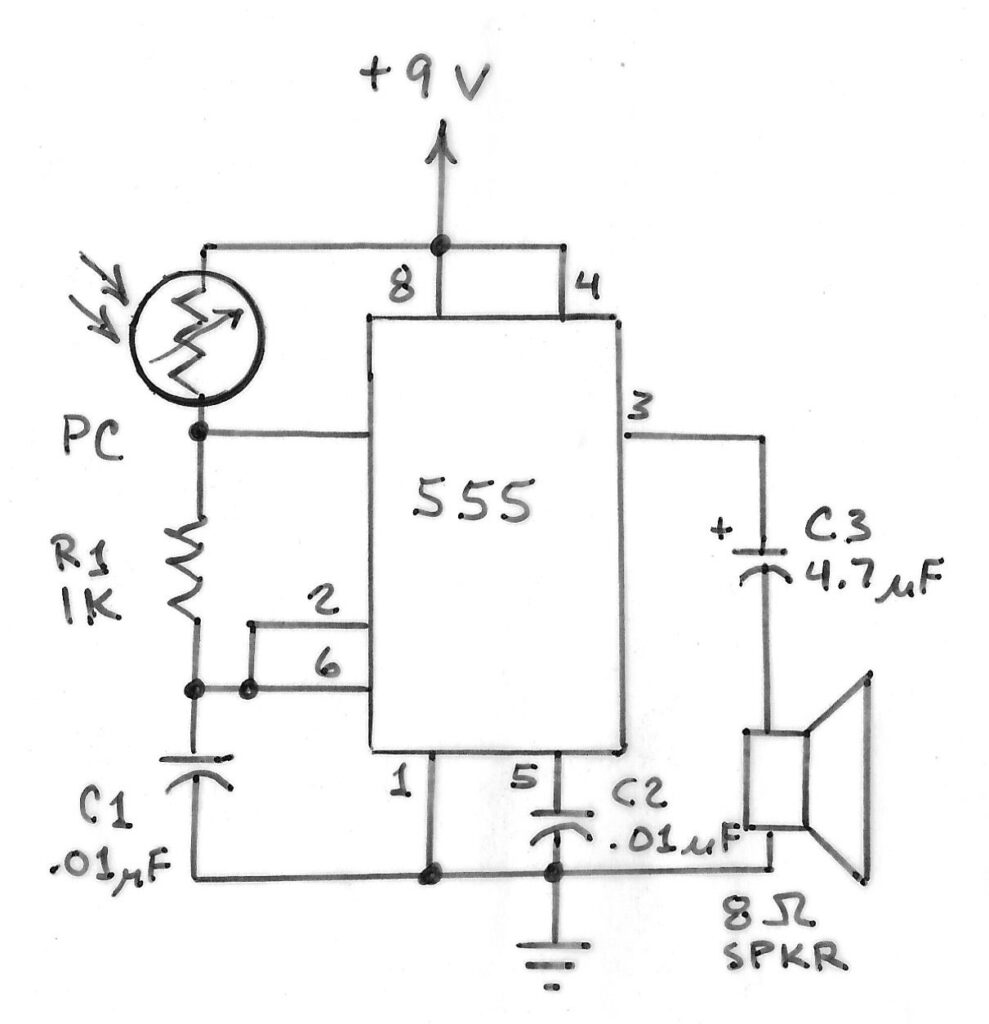
You can repeat this demonstration with the simple audio oscillator circuit shown in Figure A.
This circuit is easily assembled on a solderless breadboard. It features a 555 timer chip that’s connected to a CdS photoresistor across pins 4 and 7. You can slow the circuit’s audible frequency range by increasing the value of C1.
This circuit works best with a CdS photoresistor that has a high resistance when dark and a low resistance when illuminated. CdS photoresistors are widely available online. RadioShack offers a set of 5 (item number 2761657) with a wide range of sensitivity differences that allow you to experiment to find the best results.
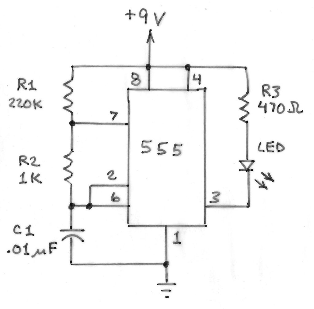
Figure B shows a light transmitter that applies a stream of pulses to an ordinary red or near IR LED at a frequency determined by R1. The values shown provide a light beam that’s modulated at about 600Hz.
Figure shows a simple light receiver that will detect the pulsating beam from the LED and convert it into an audio tone. You can use this circuit to test infrared (IR) remote controllers.
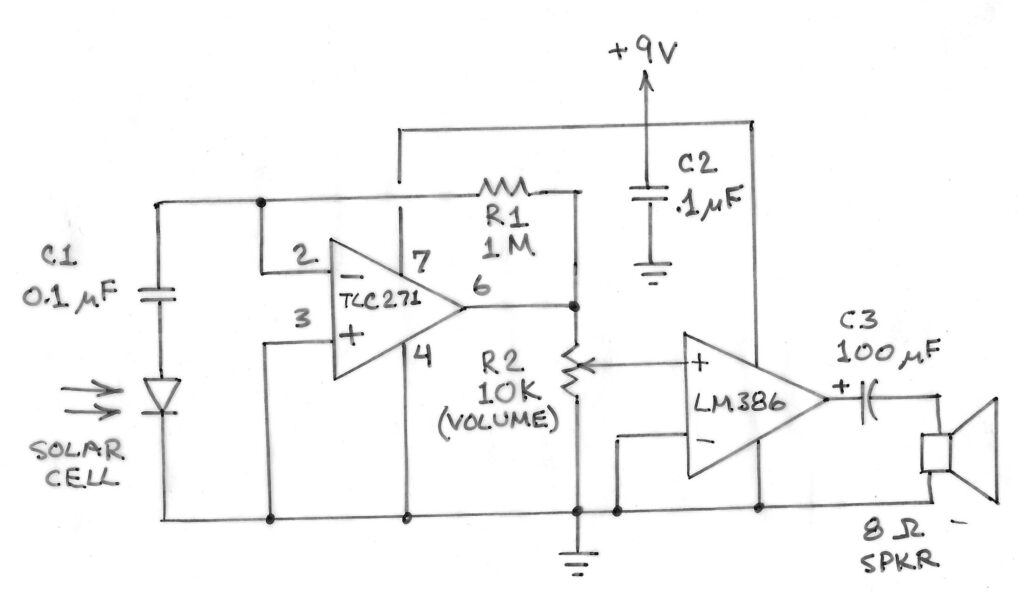
You don’t need to build the circuit in Figure C if you have a Bluetooth speaker that includes an audio input jack for an external signal. All you’ll need to make an audio frequency light receiver is a suitable detector.
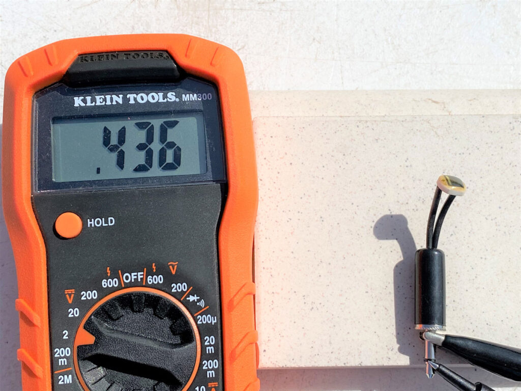
I’ve used a variety of silicon photodiodes for this purpose. A typical one is OSRAM’s BPW34. These are miniature solar cells installed in a miniature epoxy or metal package with a glass window. Figure D shows the voltage produced by a photodiode in late afternoon sunlight.
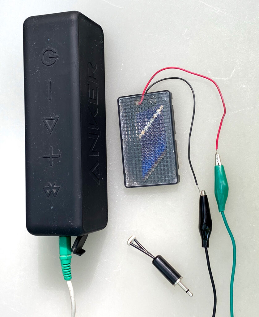
Figure E shows an Anker Bluetooth speaker connected to a silicon solar cell. The positive lead from the solar cell is connected to the tip of a 1/8″ phone plug inserted into the speaker’s input jack. The negative lead goes to the ground connection on the plug.
Figure E also shows a photodiode soldered to a phone plug that can be inserted into the speaker’s input jack. This works well for testing remote controllers. If no tone is heard from the speaker when the remote’s button is pressed, chances are the remote’s battery needs replacing.
You can even use an LED as a light-sensitive photodiode instead of a silicon light sensor. Use the same type of LED for both the transmitter and receiver. Near-IR LEDs (880nm) will work best. This is the most common LED used in remote controllers, so you can demonstrate reception of a tone-modulated IR beam simply by pointing a remote controller at the receiver’s LED.
Be sure to set the speaker’s volume to its lowest level when experimenting. A 0.5-volt silicon solar cell used as a light sensor can cause a very loud sound from the speaker!
CAUTION: Be careful if you’re connecting a solar panel that has multiple cells or an output exceeding a few volts, for the high voltage might damage your Bluetooth speaker. If you try this, insert a 0.1µF capacitor between the positive solar panel connection and the speaker’s positive input, and use the panel indoors, or outdoors only at night.
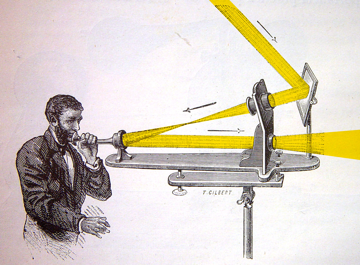
After Alexander Graham Bell invented the telephone, he pioneered ways for beams of sunlight to carry musical tones or even voice. He also pioneered the development of light receivers that converted a tone or voice superimposed onto a beam of sunlight back into sound. He called this new technology the photophone.
On February 19, 1980, my wife Minnie and I visited a small parking lot in Washington, D.C. A former building at that site was home to Bell and his wife 100 years before our visit. We were accompanied by representatives from National Geographic, the Smithsonian Institution, and Bell Laboratories. Our purpose was to recognize the first time Bell transmitted the human voice over a beam of sunlight by a photophone exactly a century earlier.
To celebrate the photophone centennial, I built a simple version of the device with which we sent our voices across the site over beams of sunlight. We then unwound a 100-foot length of optical fiber to which I had attached a red LED at each end, and we talked to one another with the red LEDs serving as both emitters and detectors of voice-modulated light.
Bell didn’t have LEDs or light-sensitive photodiodes. Instead, he made his own light detector from a cylindrical array of selenium cells he cooked on a kitchen stove. When mounted inside a reflector and connected to a telephone receiver and a battery, this simple arrangement formed a receiver capable of detecting the human voice transmitted over a beam of reflected sunlight.
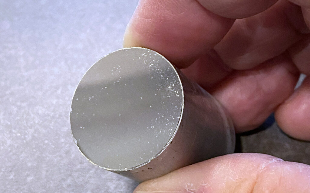
Bell devised various ways to imprint voice on a sunbeam, the simplest of which was simply a thin mirror. When voice was directed against the mirror, it vibrated in step with the sound waves. The photophone transmitter I used during the Photophone Centennial was an ultra-thin, 1″ circular mirror cemented to one end of a 1″-diameter, 1¼”-long aluminum tube (Figure F). Ultra-thin mirrors are hard to find, so an alternate will probably be required. Aluminum foil (shiny side facing out) can be taped to one end of a paper or plastic tube or cup — but the problem with foil is wrinkle prevention.
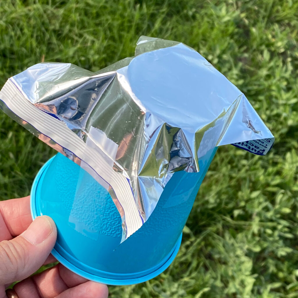
Aluminized plastic, as from a snack wrapper or a space blanket, is much easier to use. Figure G shows a plastic cup with its bottom removed and aluminized plastic taped over the removed bottom.
For your photophone receiver, you can use the circuit in Figure C or a Bluetooth speaker. For best results, use a single, large-area silicon solar cell (e.g., 2″×2″ or 4″×4″) for a detector. You want to detect only modulated sunlight, so mount the cell inside an open box or oatmeal container to block direct sunlight.
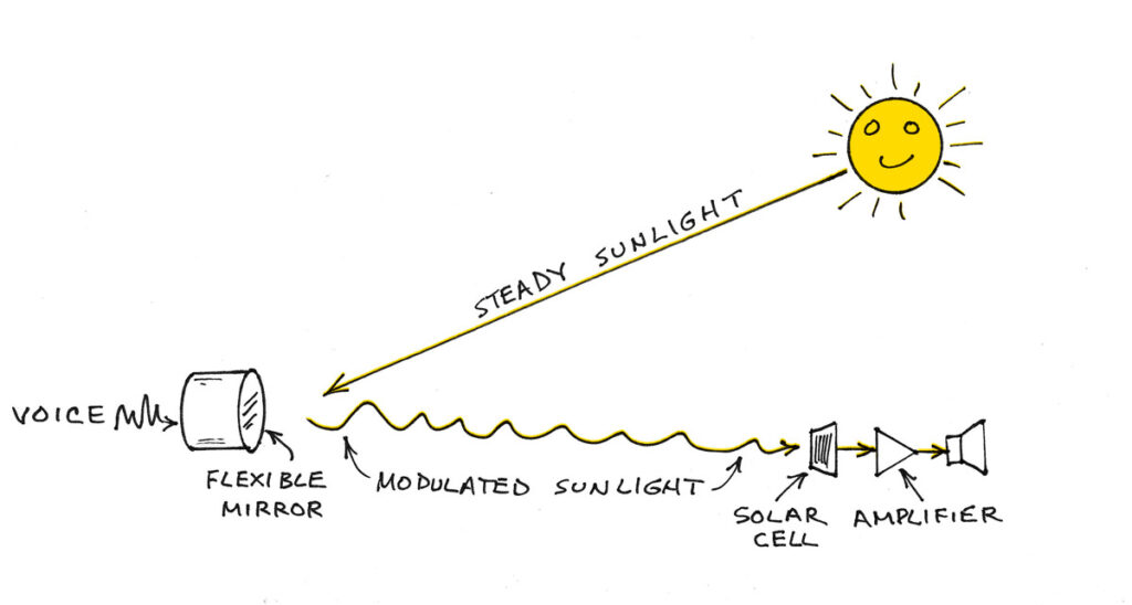
Figure H shows how the photophone is used. For initial tests, use masking tape to attach the open end of your photophone transmitter over the speaker of a battery-powered radio. Ask a friend to wear sunglasses and a reflective safety vest and stand or sit in a shaded spot while holding the receiver’s detector facing a sunny spot around 50 feet away. Walk to the sunny spot, turn on the transmitter’s radio and shine reflected sunlight toward your friend until you see the safety reflectors brighten. Your friend should then hear the radio to which the reflective transmitter is attached.
If a friend isn’t available, substitute an inexpensive safety reflector on a pole. Insert the pole in the ground in a shady spot and rotate it so the reflector faces the sunny spot. Next, go to the sunny spot and place the transmitter and radio on the ground or a tripod and tilt it until you see the reflector brightening. Then walk to the reflector and point the receiver’s solar panel toward the transmitter.
Either way, be patient. You may need to adjust or remake your transmitter so that its reflector is perfectly flat.
CAUTION: While experimenting with a DIY photophone outdoors you should wear dark sunglasses and a hat for protection, and you must never look directly at the sun or its reflection!
The DIY photophone can be used indoors along dark hallways or inside gyms if the sun is replaced by a bright, battery-powered incandescent spotlight. LED spotlights will not work as well, for silicon solar cells are most sensitive to near-IR wavelengths that white LEDs don’t emit.
This article appeared in Make: Volume 78.


