Author Note: Since the release of the article in MAKE Magazine Volume 15 in 2008, the Compressed Air Rocket has been popular beyond belief.  We’ve sold thousands of kits and Kip Kay’s Weekend Project on YouTube has over one million views!  Now we’re rolling out a Version 2.0 of the launcher as well as the much anticipated and first-of-its-kind Air Rocket Glider.  Follow us at: AirRocketWorks.com to join the air rocket community and become a backer.  – Rick Schertle (Compressed Air Rocket Designer) & Keith Violette (Air Rocket Glider Designer)

Paper, tape, compressed air … lift-off!

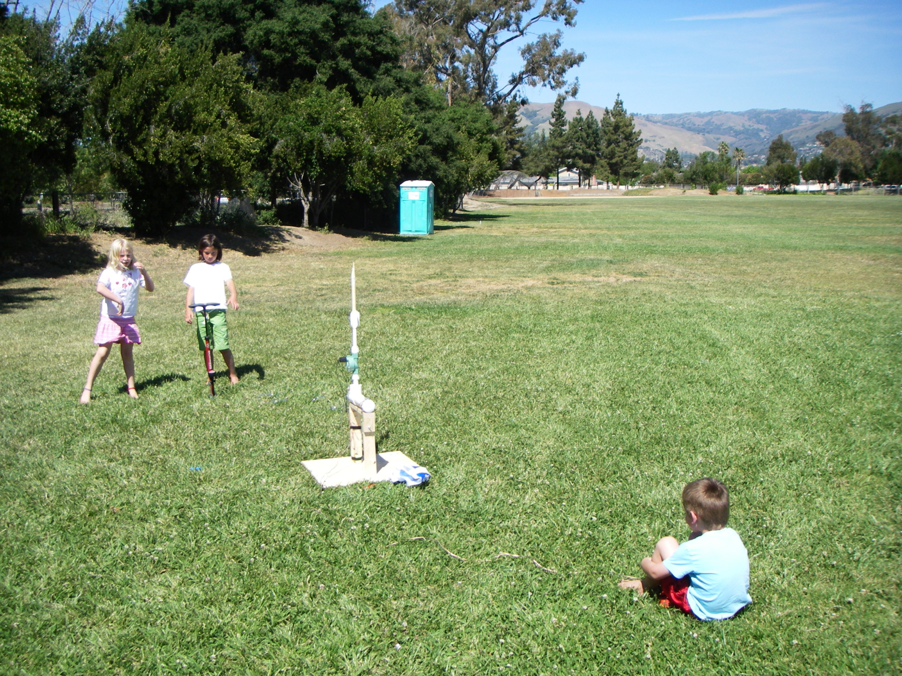
Blow your friends away as you send this 25-cent rocket hundreds of feet in the air. You can build this easy launcher and rocket with common hardware store items in an afternoon. All the parts for this simple but impressive air rocket and launcher are cheap and easy to find. Building it is a breeze and the modifications are endless. It’s legal in a big city, reusable, clean, and can be launched even in high winds on a small field. Believe me, folks are quite taken by the 200- to 300-foot flights fueled by 18 or so bicycle pumps of compressed air. Whether you’re launching on your own or with a whole group of rocketeers, watch the crowds gather … 3, 2, 1, and away! Gather materials as listed below, or get the new Compressed Air Rocket kit v2.0 at AirRocketWorks.com

Project Steps

Assemble the pressure chamber.

Use PVC primer, then cement, to glue the 2″ male slip × 3⁄4″ female slip PVC reducer bushing into the 2″ slip tee. Next, prime and glue the 3⁄4″ male slip × 1⁄2″ female threaded PVC reducer into the 2″ male slip × 3⁄4″ female slip PVC reducer bushing.

Apply teflon tape to the threads of both brass fittings. Screw the brass barbed fitting to the brass 1⁄2″×1″ reducer bushing. Screw the 1⁄2″×1″ brass reducer bushing into the 3⁄4″ male slip × 1⁄2″ female threaded PVC reducer. Tighten all connections with an adjustable wrench.

To complete the pressure chamber assembly, prime and glue the 2″ end cap onto the 10″ length of 2″ PVC pipe. Next, glue the 10″ piece of 2″ pipe into the other end of the 2″ tee as shown.

Build the launch system.

Wrap teflon tape around each of the 3⁄4″ male threaded × 3⁄4″ female slip PVC adapters. Thread the adapters onto the 3⁄4″ inline 24V electric sprinkler valve and tighten with channel-lock pliers.

Cut a 3″ length of 3⁄4″ PVC and a 16″ length of 1⁄2″ PVC. Glue the 3″ piece into the “In” side of the sprinkler valve. Glue the 3⁄4″ male slip × 1⁄2″ female slip reducer and the 16″ length of 1⁄2″ PVC into the “Out” side of the valve.

Glue the 2″ male slip × 3⁄4″ female slip PVC reducer bushing into the tee on the pressure chamber.

Glue the completed launch assembly into the pressure chamber. Your air launch system is complete.

Build the launch tower and attach the launch system.

Cut your 3⁄4″×3″ lumber to the following lengths: 15″ (1), 3 1⁄2″ (2), and 12″ (2).

Clamp a 3 1⁄2″ length to the 15″ length as shown. Pre-drill 2 holes with the 3/32″ bit and then screw in the 1 1⁄2″ screws using a drill/driver. A bit of wood glue would be good too, if available. Repeat with the other 31⁄2″ length on the other side.

Mark a 3 1⁄2″ piece 1″ from the bottom, mark a 12″ piece 2″ from the top, line them up, and sandwich them together using a C-clamp. Drill a 1⁄4″ hole through both pieces, then slip a 1⁄4″ hex bolt through, with washers on both sides and a wing nut on the outside. Repeat on the other side.

The 24″×24″ piece of plywood will provide a sturdy base for the launch tower. Measure and mark a line down the center of the plywood, 12″ in from either side. On your centerline, mea- sure and mark 4 1⁄2″ in from both ends. Place the legs of the launch tower with their edges on the inside of the marks, then trace a line around each leg. Drill two 3/32″ holes in each traced area.

Turn the whole thing upside down, line up the launch tower on the marks, and then finish drilling pilot holes into the launch tower legs, through the existing holes in the plywood. Screw into place.

Once your base is secure, attach the pressure chamber/launch system to the horizontal board using the 2 large hose clamps. Your launch tower is complete.

Make and wire the launch button.

Drill a 1⁄4″ hole in the middle of one 3⁄4″ PVC slip end cap, and drill a 1⁄2″ hole in the middle of the other to accommodate the button switch.

Thread the paired wire through the end cap with the smaller hole, from the outside, and tie a knot about 8″ from the end, so the knot is inside the cap. Now thread the end of the wire in the following order — through the 4″ piece of 3⁄4″ PVC, through the nut and washer for the button, then through the 1⁄2″ hole in the other 3⁄4″ end cap, from the inside.

Solder the wire ends to the leads on the bottom of the button. Slip the washer and nut over the button, inside the PVC cap, and tighten the nut using a pair of needlenose pliers. This can be a bit tricky.

Connect the wiring.

Solder connections when possible, and insulate them with electrical tape.

Use bullet connectors or something similar to connect the battery leads to the button and the electric valve.

Connect 1 wire from the button to 1 lead on the sprinkler valve. Twist, then solder and/or tape.

Connect the other wire from the button to one of the bullet connectors on the battery leads (red or black, it doesn’t matter).

Connect the remaining battery connector to the remaining lead on the sprinkler valve.

Tape the wire for the button to the vertical support of the launch tower. Test your launch button. When you press the button, you should hear the sprinkler valve click open and closed. You’ll do more testing later when the system is under pressure.

Make the air hose and test the launch system.

Now we’re going to assemble and attach the air hose to the launcher. First, strip the rubber off the tire valve. You can use fine sandpaper to clean off the valve so it’s shiny.

Slip the tiny hose clamp over the hose and insert the tire valve into the hose. Push it in as far as you can. Tighten the hose clamp over the tube and valve using a socket or screwdriver. This connection was the Achilles’ heel in my prototype launcher. Granted, it was exciting to have the hose explode off at 75psi, hissing wildly like a snake, but, for the sake of reliability, I’ve strengthened it by using the mini hose clamps.

Slip the second mini hose clamp over the other end of the hose, and push the hose end onto the 6″ hose barb. Tighten the clamp over the hose and barb. If you find the clamp too big and you’re not able to get it really tight, wrap the barb in rubber from a bike inner tube and then tighten the clamp over that.

Attach the bicycle pump to the tire valve and pressurize the system to about 75psi. Keep an eye on the gauge and listen for any hissing. The pressure should stay at 75psi. If you find leaks, fix them and try again.

Release the pressure by pressing the launch button (with the battery connected). Be careful when you do this — wear eye protection and stand clear of the pressure chamber.

If the pressure doesn’t release when you press the button, tighten down the solenoid (the black thing with the wires coming out) on the sprinkler valve. You may also need a larger battery (one with more amps) to trigger the solenoid under pressure.

If you’re still having problems with your electrical system, most valves have a manual trigger you can flip to release the pressure. If you’re up this close to the valve you may want hearing protection as well. Be very careful that your head is away from the launch tube.

Build the rocket assembly stand.

Mark the center of a 5 1⁄2″ scrap of 2×6 lumber. Drill a 13/16″ hole 1″ deep in the center. This is where a drill press is really handy. Then twist a 13″ length of 1⁄2″ PVC pipe into the hole. Add masking tape to the base of the pipe, if needed, to get a snug fit.

Build the rockets.

Download the rocket template and print it out on 8 1⁄2″×14″ paper. Cut out all the pieces on the solid lines as shown.

Wrap the body tube around the assembly stand and tape it in 5 places with the 3⁄4″ masking tape. The smoother your tape, the more aerodynamic your rocket will be. Now wrap the body tube with 2″ masking tape, working your way down. Slide the body tube to the top of the PVC stand. Tape the pressure cap on top of the body tube by crisscrossing 3⁄4″ tape over the top, and smooth it down.

Curl the nose cone around to overlap the dotted section, and tape it in place. Stuff the nose cone tightly with the napkin. A full napkin should fit in. Use a pencil to pack it tightly.

Place the nose cone on top of the body tube, tape around the tabs, then cover the nose cone in tape.

Wrap the fin guide around the PVC pipe at the base of the body tube and mark on the 3s for a 3-fin model or the 4s for 4 fins.

Fold the fins on the dashed lines, then stack them together and trim the tops and bottoms at an angle.

Glue the fins together with a glue stick, and pinch them to adhere them. Make sure you don’t glue the tabs that will be used to attach the fins to the rocket.

Line up the fins with the marks on the bottom of the body tube. Tape all fins securely in place.

Your rocket is now complete and ready to launch. The great thing about these rockets is that no matter how they’re built, they will fly! Some of course will fly better than others, but they all will fly to some degree.

Conclusion

This project first appeared in MAKE Volume 15, page 102.