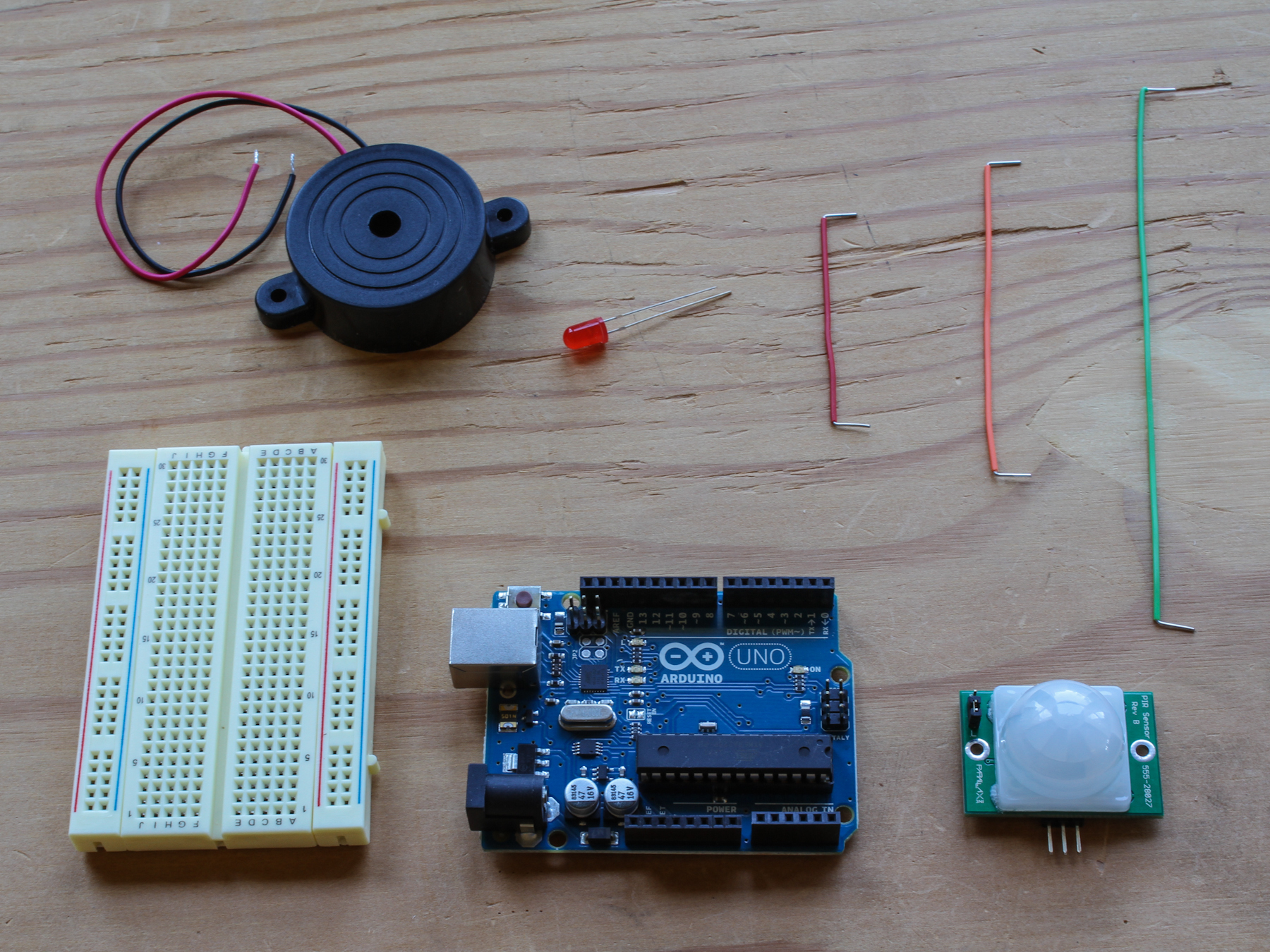
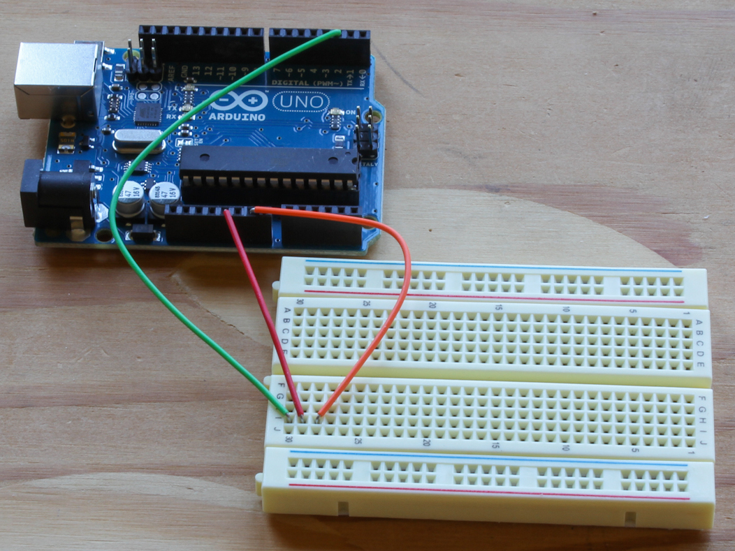
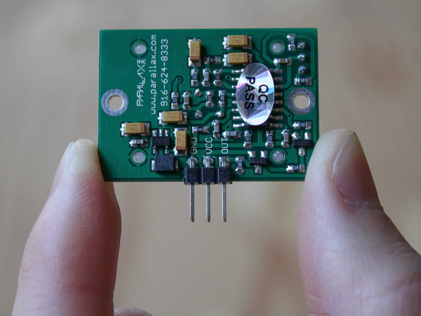
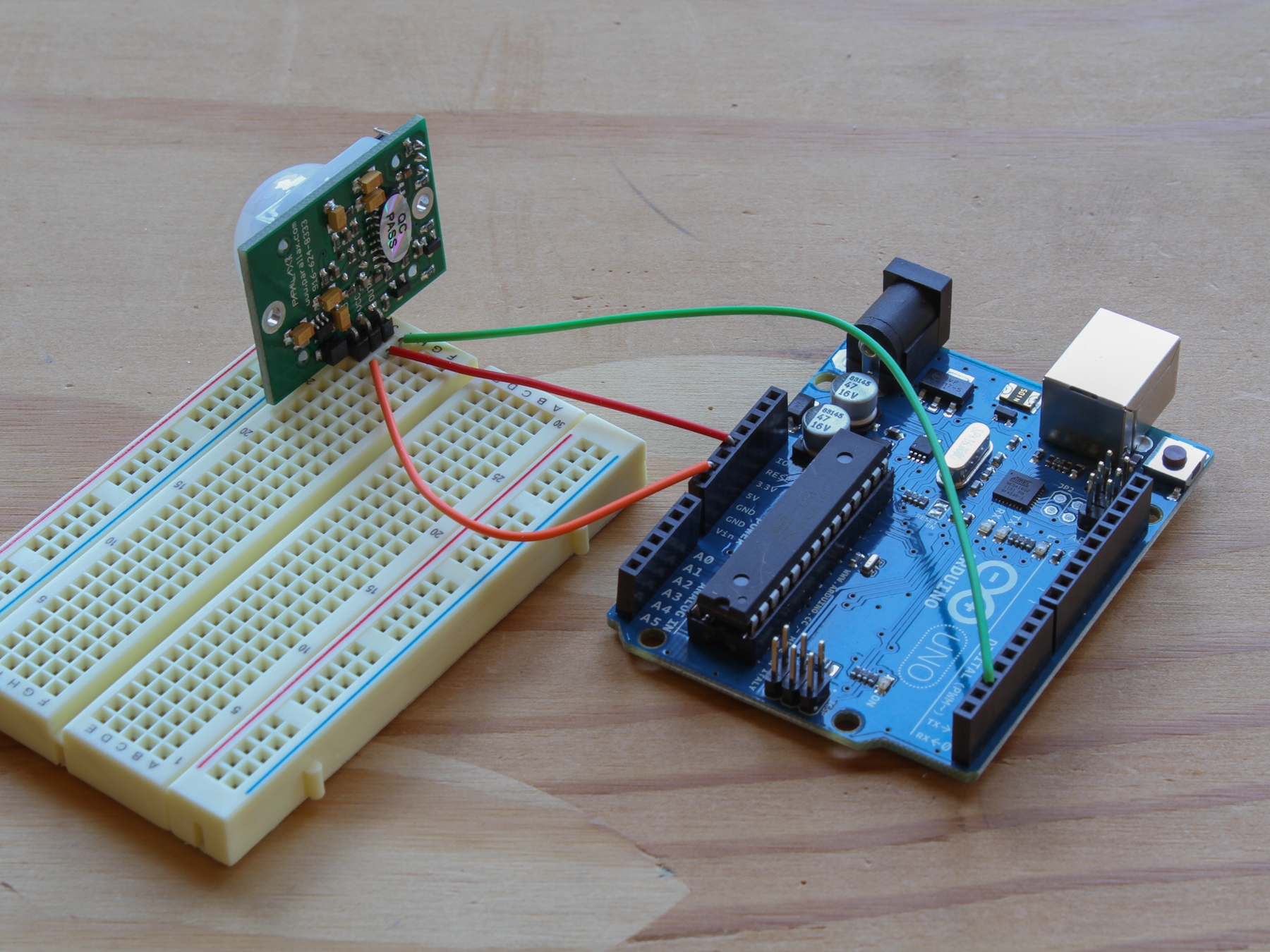
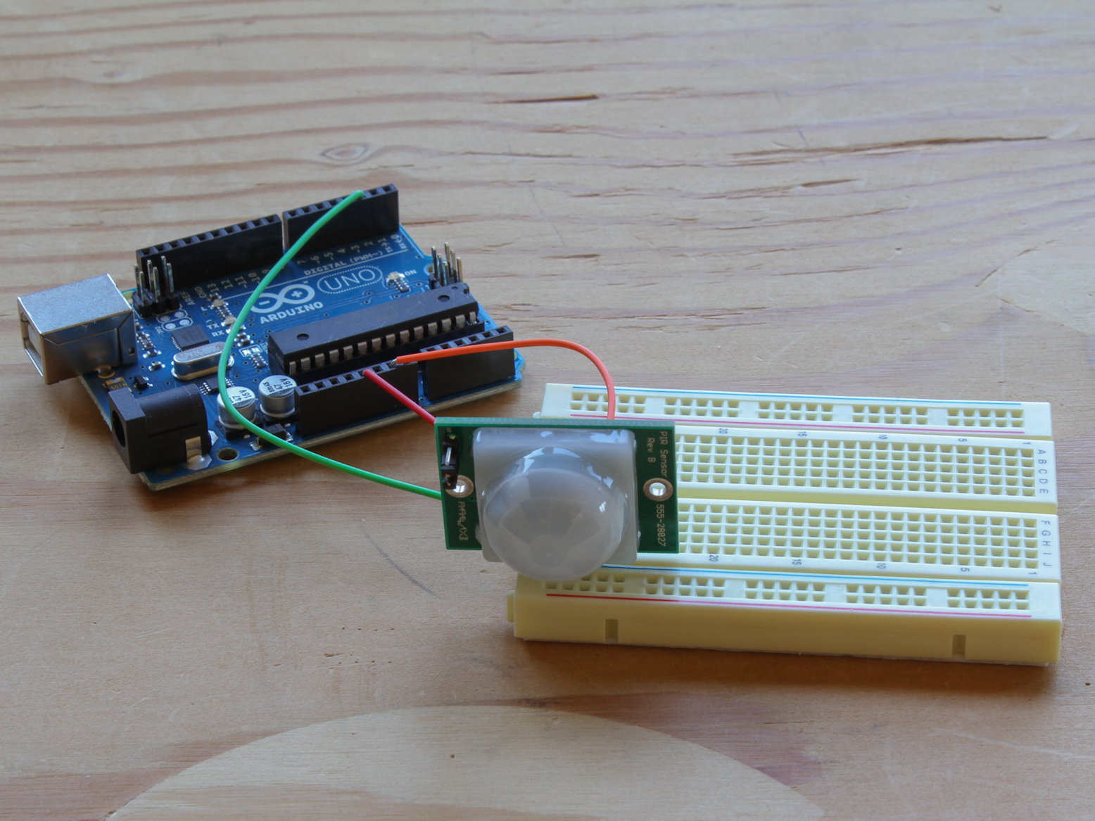
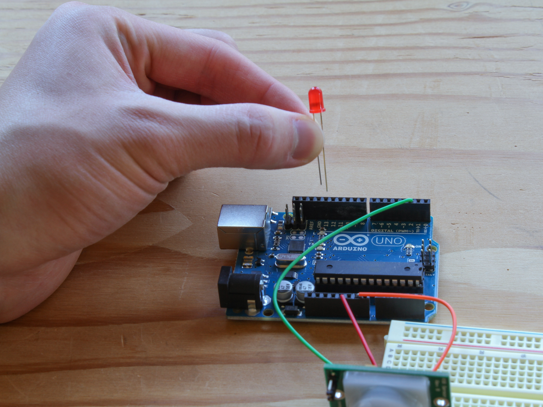
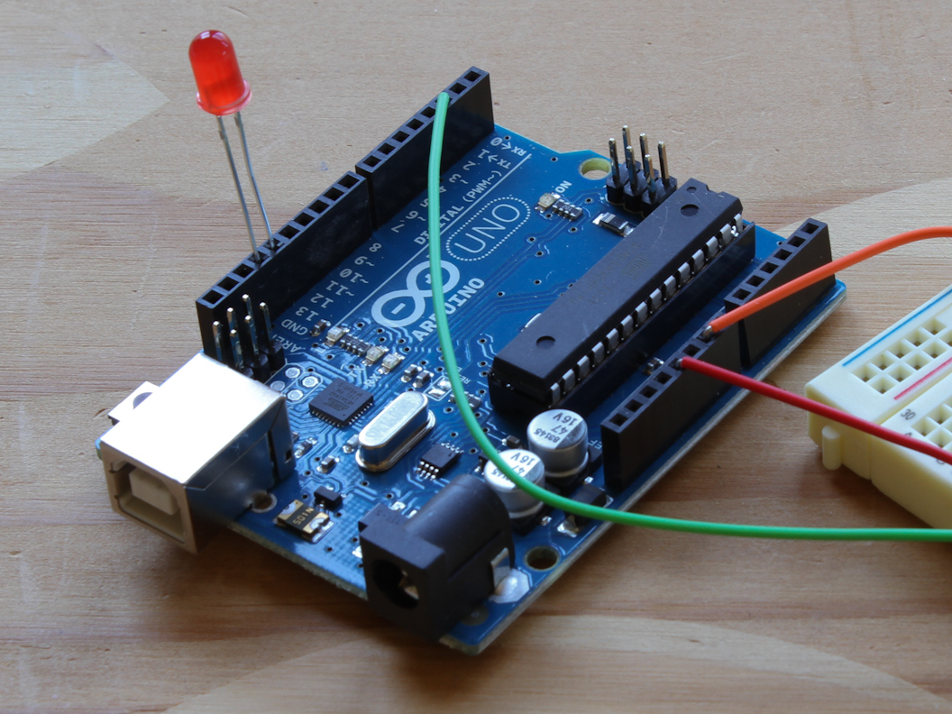
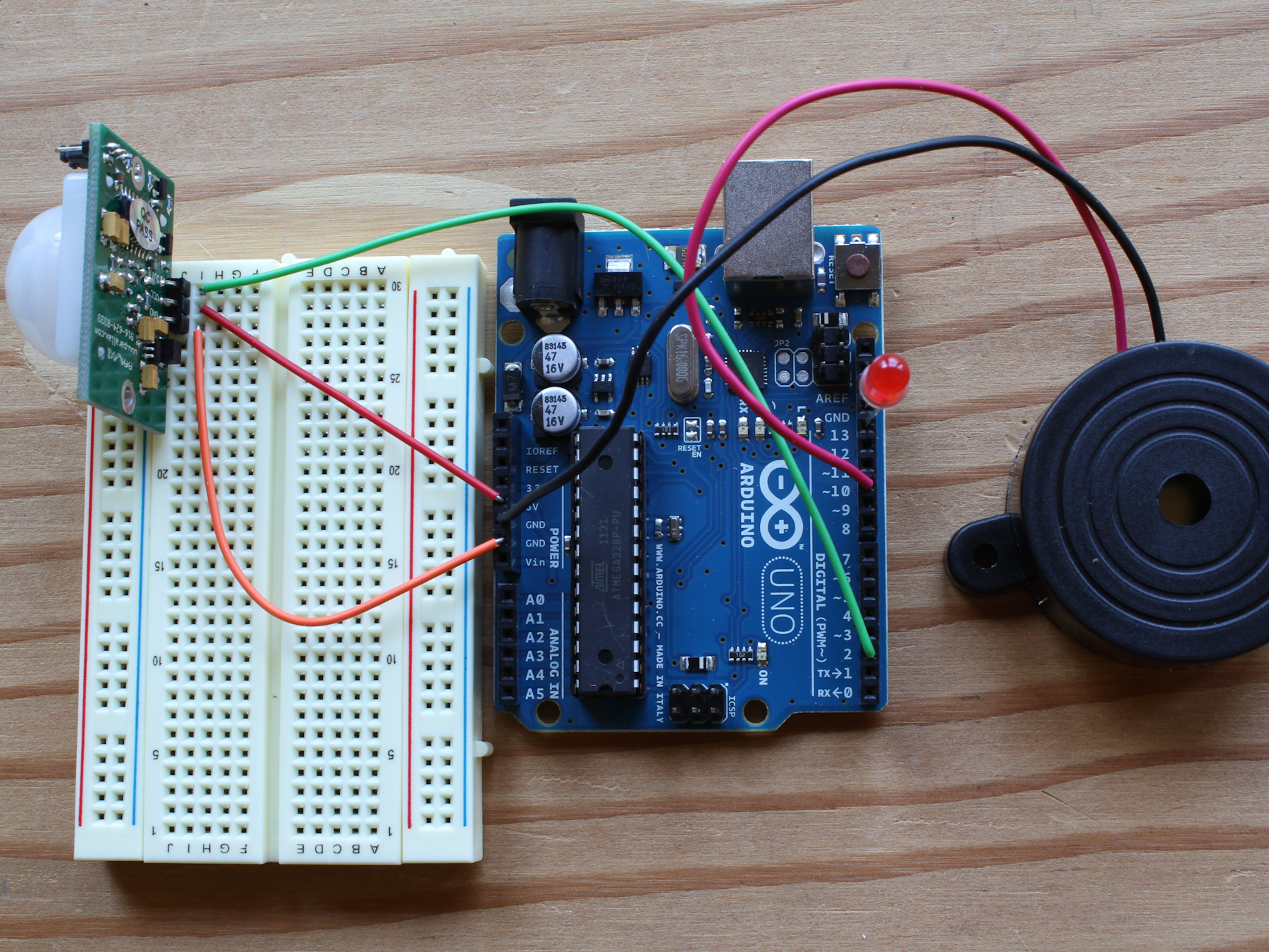
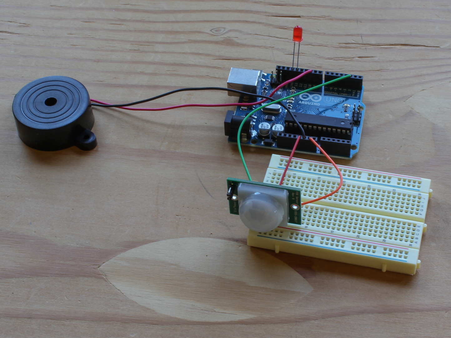
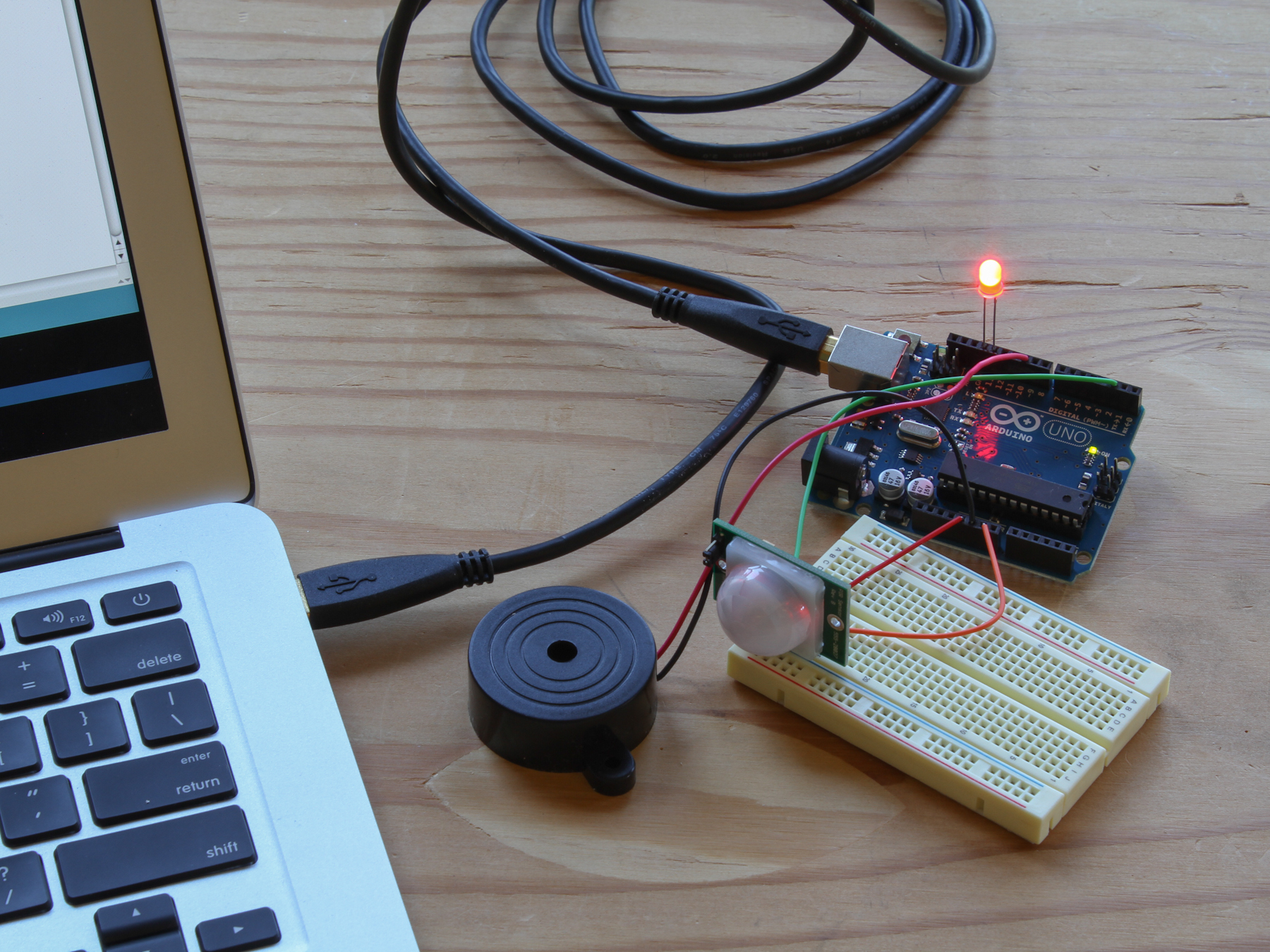
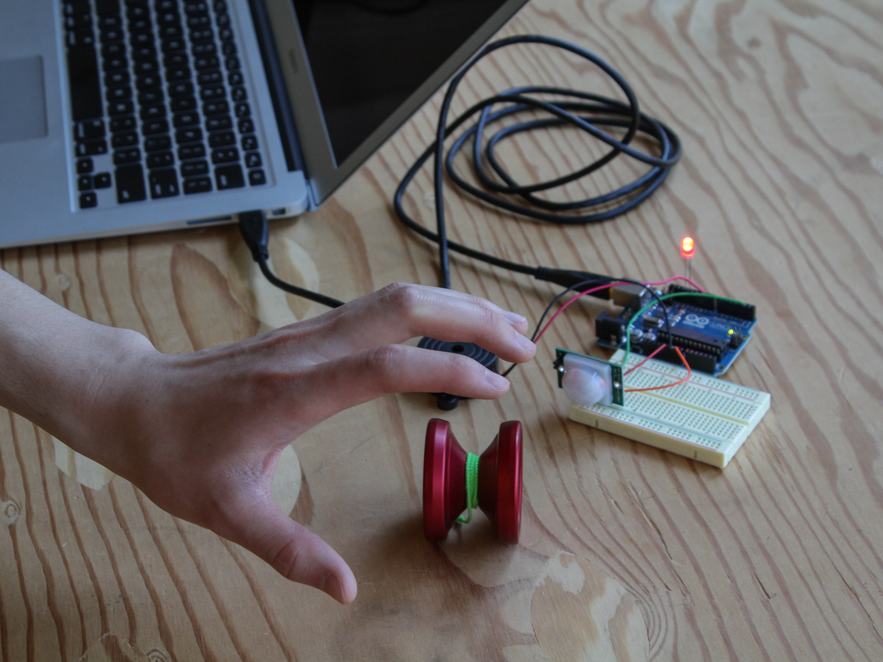
In this simple project, we’ll build a motion-sensing alarm using a PIR (passive infrared) sensor and an Arduino microcontroller. This is a great way to learn the basics of using digital input (from the sensor) and output (in this case, to a noisy buzzer) on your Arduino.
This alarm is handy for booby traps and practical jokes, and it’s just what you’ll need to detect a zombie invasion! Plus, it’s all built on a breadboard, so no soldering required!
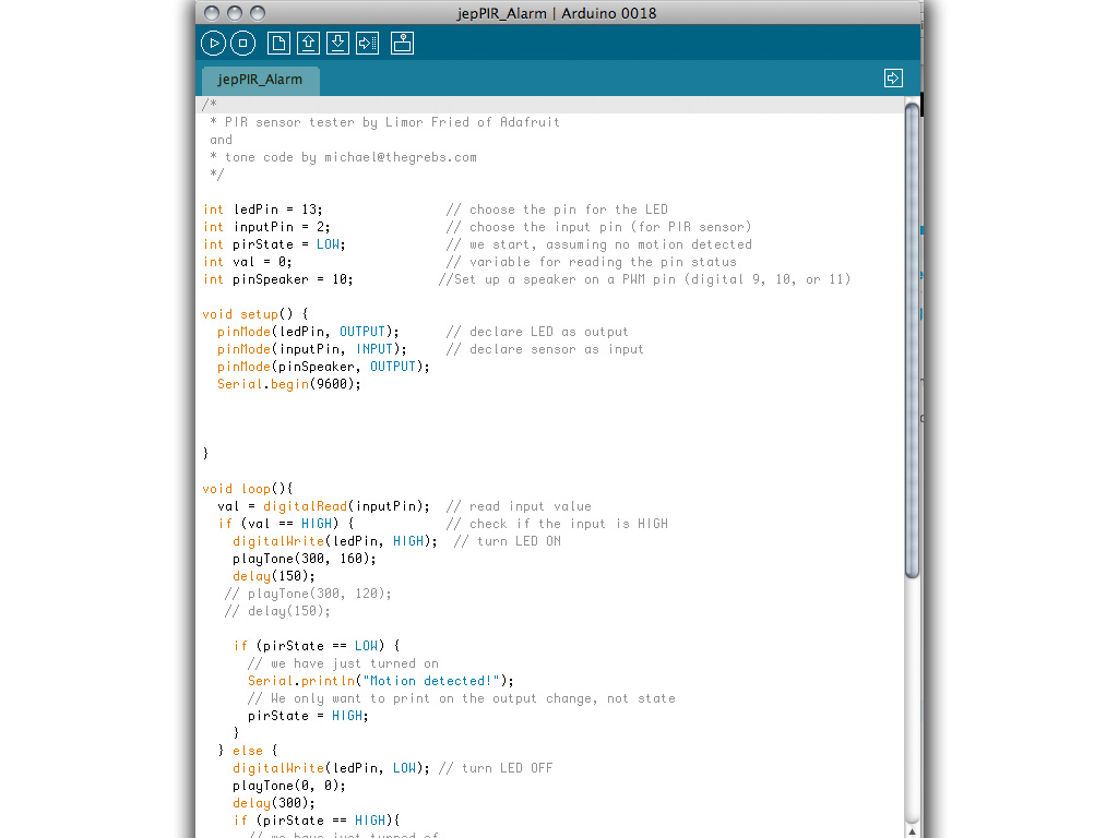
This project requires just a few parts, and because you're using a solderless breadboard and pre-cut jumper wires, you won't need any tools at all — except your computer and USB cable to connect the Arduino.
Find the Gnd (–), Vcc (+), and Out pins on the PIR sensor.
Plug the PIR sensor into the breadboard so that its (–) pin connects to the Gnd row, its (+) pin connects to 5V, and its Out pin connects to digital pin 2.
NOTE: If you have a different sensor than the one shown here, you may need to extend the sensor's pins with a stacking female header, wires, interconnect cables, etc. to fit.
Launch the Arduino IDE software. You can download it for free here.
Plug the USB cable into your computer and Arduino.
Set the board and port settings for your Arduino board, in this case, an Arduino Uno.
Open the PIR Alarm sketch found at this link: https://raw.github.com/jedgarpark/Make_PIR_Sensor/master/MAKE_PIR_Sensor.pde
(Arduino programs are called sketches.)
Upload the sketch to the Arduino.
Step #7: Test your alarm.
When you power up your alarm, the PIR sensor will glow an ominous red. Stand very still or leave the room while the alarm calibrates the infrared level reading for the room.
Now test it by moving: the buzzer will buzz and the LED will light up.
Be amazed! Your PIR Sensor Arduino Alarm can sense movement up to 20 feet away. No one will be stealing your yo-yo today.
NOTE: Might not be reliable for detecting the undead.
Brandon, sorry for the huge delay, I didn’t see your comment until now. You can change the delay time upon startup to be longer if you need. Try adding a new line as the first one in the void setup that reads: delay(5000);
That’ll give you five seconds before it begins.
I noticed when I took the code from the PDF, the formatting was off when it is copy/pasted into Arduino editor. Best to download the PDE which is on the right side of the page above.
Hi, nice project, im looking to do an attack sensor so its very similar to this, my components are fairly simialar, just wanted to know will they work if swtiched with the ones in the project youve used, im using a vibrations motor as the output, and a sharp PIR sensor for the input, any help or advice will be great and really appreciated.
The Sketch seems to have been removed from the page. Does anyone know where? I even did a search for “pdf” in the source code of this page without a result (sorry Goli Mohammadi).
int ledPin = 13; // choose the pin for the LED
int inputPin = 2; // choose the input pin (for PIR sensor)
int pirState = LOW; // we start, assuming no motion detected
int val = 0; // variable for reading the pin status
int pinSpeaker = 10; //Set up a speaker on a PWM pin (digital 9, 10, or 11)
void setup() {
pinMode(ledPin, OUTPUT); // declare LED as output
pinMode(inputPin, INPUT); // declare sensor as input
pinMode(pinSpeaker, OUTPUT);
Serial.begin(9600);
}
void loop(){
val = digitalRead(inputPin); // read input value
if (val == HIGH) { // check if the input is HIGH
digitalWrite(ledPin, HIGH); // turn LED ON
playTone(300, 160);
delay(150);
if (pirState == LOW) {
// we have just turned on
Serial.println(“Motion detected!”);
// We only want to print on the output change, not state
pirState = HIGH;
}
} else {
digitalWrite(ledPin, LOW); // turn LED OFF
playTone(0, 0);
delay(300);
if (pirState == HIGH){
// we have just turned of
Serial.println(“Motion ended!”);
// We only want to print on the output change, not state
pirState = LOW;
}
}
}
// duration in mSecs, frequency in hertz
void playTone(long duration, int freq) {
duration *= 1000;
int period = (1.0 / freq) * 1000000;
long elapsed_time = 0;
while (elapsed_time < duration) {
digitalWrite(pinSpeaker,HIGH);
delayMicroseconds(period / 2);
digitalWrite(pinSpeaker, LOW);
delayMicroseconds(period / 2);
elapsed_time += (period);
}
}
Thanks this is simple and neat. My nine year old son wanted to “invent” a device that scared off the birds under our deck so they didn’t make nests. So we used these plans. Going to try an add a camera to snap pics of it scaring off birds. Though knowing these birds they’ll just make a nest on top of it.
Scrap that, I worked out whats wrong. Essentially I am an idiot, I had opened the code up in Processing and not Arduino. Can someone tell me how to add a Camera to take photos to this please?
One straightforward way would be to use a camera that has an input for a remote switch, and have the Arduino close that for you with a transistor or relay. I made my own release switch: http://blog.makezine.com/2010/11/10/john-edgar-park-has-a-trigger-mouth/ using a 2.5mm phone earbud, you’d trigger it with the Arduino instead of the arcade button.
It’s a PDF under Files at the top of the project. Have fun!
If you have the code then send me on this address email “mf93@live.it” please!!
where is the code. Plz HURRY
For Real
i tried downloading the sketch and its no where to be found…anyone know. this is probably something simple, right? yea whatever….
Brandon, sorry for the huge delay, I didn’t see your comment until now. You can change the delay time upon startup to be longer if you need. Try adding a new line as the first one in the void setup that reads: delay(5000);
That’ll give you five seconds before it begins.
I noticed when I took the code from the PDF, the formatting was off when it is copy/pasted into Arduino editor. Best to download the PDE which is on the right side of the page above.
Hi! Nice project! wanna try it too.. but the thing is, I don’t know where to download the code.. I can’t find it…..
“Were Is The Code I Can’t Find It”?
Sorry about that, we’re looking into what happened. It seems when the new formatting was introduced the code was no longer included.
Hi, nice project, im looking to do an attack sensor so its very similar to this, my components are fairly simialar, just wanted to know will they work if swtiched with the ones in the project youve used, im using a vibrations motor as the output, and a sharp PIR sensor for the input, any help or advice will be great and really appreciated.
Hello, please send me the program?
e-mail: robert-1406@hotmail.com
The Sketch seems to have been removed from the page. Does anyone know where? I even did a search for “pdf” in the source code of this page without a result (sorry Goli Mohammadi).
Is there code for this yet?
I found the code here: http://make-documents.s3.amazonaws.com/fv1fYSLfy6QRgANM.pdf
Hello, send me the code? Please.
elany7@gmail.com
cant download this pir sensor sketch, whats the deal? someone let me know just how much of an idiot iam?
Sorry for the delay in fixing the post. Here is the code, I’ll see about having it properly added to the project next.
// Uses a PIR sensor to detect movement, buzzes a buzzer
// more info here: http://blog.makezine.com/projects/pir-sensor-arduino-alarm/
// email me, John Park, at jp@jpixl.net
// based upon:
// PIR sensor tester by Limor Fried of Adafruit
// tone code by michael@thegrebs.com
int ledPin = 13; // choose the pin for the LED
int inputPin = 2; // choose the input pin (for PIR sensor)
int pirState = LOW; // we start, assuming no motion detected
int val = 0; // variable for reading the pin status
int pinSpeaker = 10; //Set up a speaker on a PWM pin (digital 9, 10, or 11)
void setup() {
pinMode(ledPin, OUTPUT); // declare LED as output
pinMode(inputPin, INPUT); // declare sensor as input
pinMode(pinSpeaker, OUTPUT);
Serial.begin(9600);
}
void loop(){
val = digitalRead(inputPin); // read input value
if (val == HIGH) { // check if the input is HIGH
digitalWrite(ledPin, HIGH); // turn LED ON
playTone(300, 160);
delay(150);
if (pirState == LOW) {
// we have just turned on
Serial.println(“Motion detected!”);
// We only want to print on the output change, not state
pirState = HIGH;
}
} else {
digitalWrite(ledPin, LOW); // turn LED OFF
playTone(0, 0);
delay(300);
if (pirState == HIGH){
// we have just turned of
Serial.println(“Motion ended!”);
// We only want to print on the output change, not state
pirState = LOW;
}
}
}
// duration in mSecs, frequency in hertz
void playTone(long duration, int freq) {
duration *= 1000;
int period = (1.0 / freq) * 1000000;
long elapsed_time = 0;
while (elapsed_time < duration) {
digitalWrite(pinSpeaker,HIGH);
delayMicroseconds(period / 2);
digitalWrite(pinSpeaker, LOW);
delayMicroseconds(period / 2);
elapsed_time += (period);
}
}
Would it be possible to just run this off a battery?
Yes, you could run this off of batteries. I’ve done so and it works fine. I usually use 4 AA NiMH batteries.
can you give me pir for 8051 controller
Thanks this is simple and neat. My nine year old son wanted to “invent” a device that scared off the birds under our deck so they didn’t make nests. So we used these plans. Going to try an add a camera to snap pics of it scaring off birds. Though knowing these birds they’ll just make a nest on top of it.
Excellent, did you and your son build the Duck Alarm?
Hi, I seem to have trouble running the code it says “Cannot find anything named LOW” I have copied the code over, any idea what might be wrong?
Scrap that, I worked out whats wrong. Essentially I am an idiot, I had opened the code up in Processing and not Arduino. Can someone tell me how to add a Camera to take photos to this please?
One straightforward way would be to use a camera that has an input for a remote switch, and have the Arduino close that for you with a transistor or relay. I made my own release switch: http://blog.makezine.com/2010/11/10/john-edgar-park-has-a-trigger-mouth/ using a 2.5mm phone earbud, you’d trigger it with the Arduino instead of the arcade button.
is there a way you could switch the speaker with a servo easily?
Great project!
I was wondering if anyone could help me tweak the arduino sketch?
What code could I insert to make it so that there is a 3 second delay between the PIR receiving a signal and the outputs?
// What's Trending
Raspberry Pi Design Contest
Seventeen Sneaky Secret Hides
Lost PLA Casting from 3D Prints
Ten Tips for Adhesive Tape
10 Things to Connect to Your Raspberry Pi
Is it a Hackerspace, Makerspace, TechShop, or FabLab?
I Have a (Puzzling) Dream
Teardrop Camper Trailer
// What's Shared
A better way to slice a pumpkin
DIY Nerf Darts
100 Dollar Store Organization Ideas for Craft Rooms and Beyond
In the Maker Shed: Minty Boost USB Charger
Mad’s Mouse House
Lace Princess Crowns
I Have a (Puzzling) Dream
Play the Rings of a Tree Trunk Like a Record
// Most Commented
DIY Hacks & How To’s: Get Emergency Power from a Phone Line
Resin Casting: Going from CAD to Engineering-Grade Plastic Parts
Ten Tips for Screws and Screwdrivers
Is it a Hackerspace, Makerspace, TechShop, or FabLab?
Ten Tips for Better Measurement
Makers on TV: Big Brain Theory
Arduino Announces New Wireless Linux Board
Grow: A Portable CNC Router System
Trending Topics
Get our Newsletters
About Maker Media
Subscribe
to MAKE!
Get the print and digital versions when you subscribe