The Supercap Racer is fast, unpredictable, and fun to build!
Designed by George Albercook (founder of Rocks and Robots) and manufactured by MAKE, the Supercap Racer is a great way to hone your soldering skills, and have some fun.
Start by adding the motors. There are (2) motors and they are soldered to the PCB at locations "Motor A" and "Motor B". The "tabs" of the motors will eventually be soldered to the small square pads on the PCB. There are (4) small square pads on the PCB.
Start by adding a small amount of solder to the small square pads where the tabs of the motors will sit on the PCB (see red circle markers in picture #2)
Next, while holding the motor in place, heat the small metal tab of the motor, melting the solder on the PCB. (see picture #3)
Insert the switch from the same side the motors are mounted on.
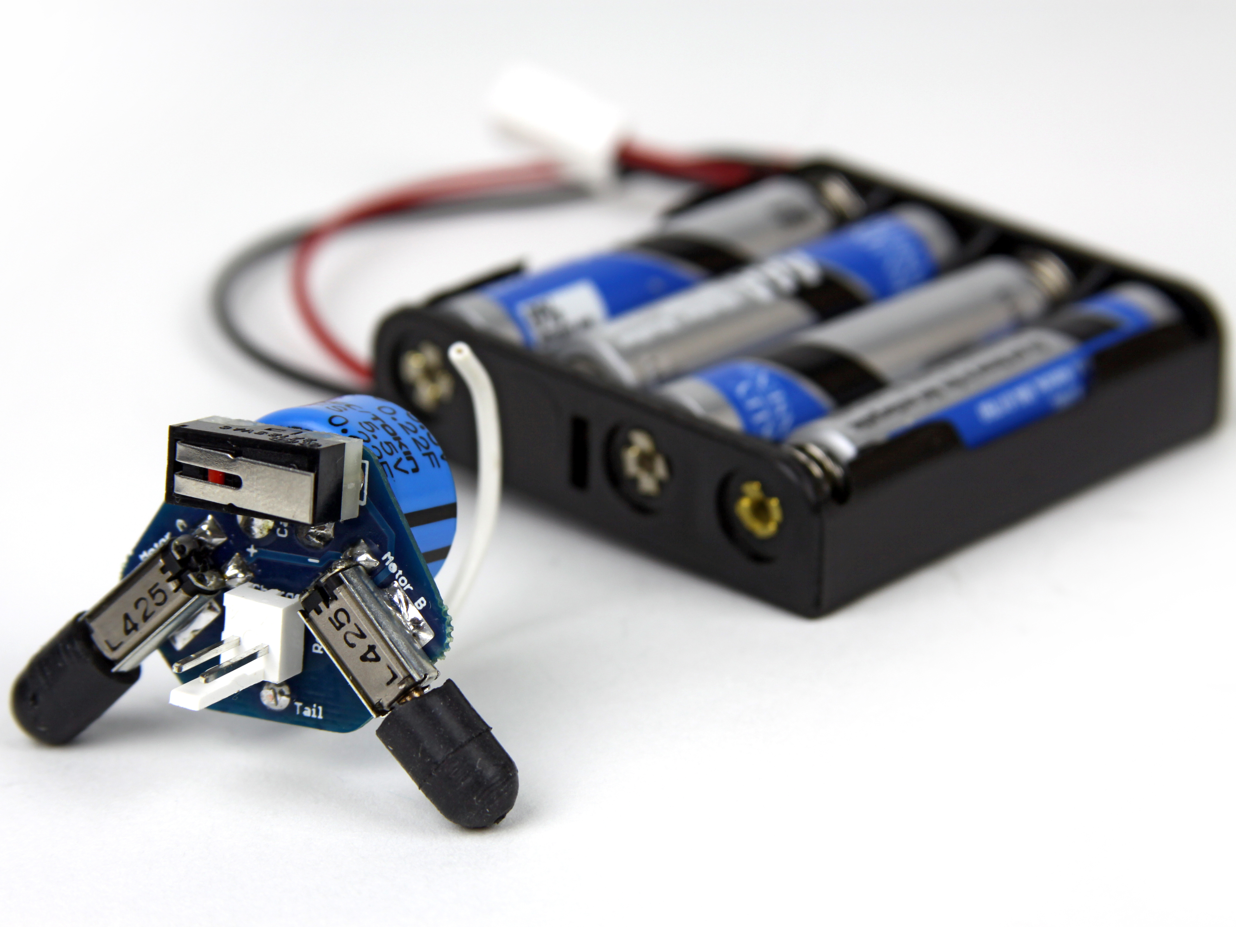
The switch needs to be inserted as pictured.
When looking at the switch from the front (as in picture #1) you should see a small red button through the metal tab. This small red button should be on the left side of the switch.
The metal tab should angle up towards the right.
Solder the switch to the PCB from the back. You might have to hold it down firmly so it lays flat against the PCB.
Once soldered, trim the leads of the switch close to the PCB.
The supercap gets inserted into the back of the PCB.
Make sure the lead marked with the black stripe is inserted into the hole marked with a (-) sign. This super-cap's (-) lead is longer, which is the opposite of most electronics parts, where the longer lead is usually (+).
One last time! The lead with the black stripe is the (-) lead!
The connector should be attached to the wires in your kit. You can see how it can be removed in picture #2. For now keep it attached.
Insert the connector from the front of the PCB, with the red wire on the right. The PCB is labeled (+) too!
Flip the PCB over and solder the connector to the board. It will be close to the super-cap, but don't worry; there will be just enough room to solder the connections.