Hello. I am currently a third year undergraduate in EECS at the University of California, Berkeley and my hobbies range from target archery to tinker and making whatever I can.
During the summer last year, I got a chance to visit and explore the beautiful University of California San Diego campus. Among the many spectacular art installations and architectural wonders on campus, there was one I could not forget. In the campus’ central hub, the Price Center, a mural of clocks is drawn across the building’s enormous walls. Most interesting however were the LED display marquee signs that interrupted the mural halfway up the walls. Sitting on a couch across the way, I could not stop staring at the news that scrolled across them. Never had I had such desire to continue reading. And then I knew, I had to have one of my own.
Going the traditional route of buying one wasn’t an option as I soon discovered, so I thus decided to cut costs and build my own.
I knew from the start that I wanted a relatively long display, so whatever I designed circuit-wise had to be able to be modular and extensible. Rather than taking a design oriented direction, I jumped straight into building with a basic idea of how everything worked in my head. With an order of 100 8×8 bicolor LED matrix modules from eBay, my journey had started.
The circuit was simple, using shift registers to drive both columns and rows in a multiplex fashion such that only one row at a time was lit, only three lines of data are needed to drive the display. Being naive, I ventured down the path of hand wiring every single module in the modular display system by hand on a perf board. By the end of the first prototype I knew that this was a nigh on impossible task as I had set out to create at least ten of these modules, and the first one looked like the following picture after an entire month of work.
Realizing this, I set out to create a digital design of the circuit which I would then hand etch. The first part of this new saga was that I had to somehow drill the thru-holes of the PCB. With no access to a proper drill press, I ventured to build my own. Sourcing a motor and motor controller from eBay and a Dremel drill press attachment, I created the following contraption to drill the thousand holes that would be on each module board.
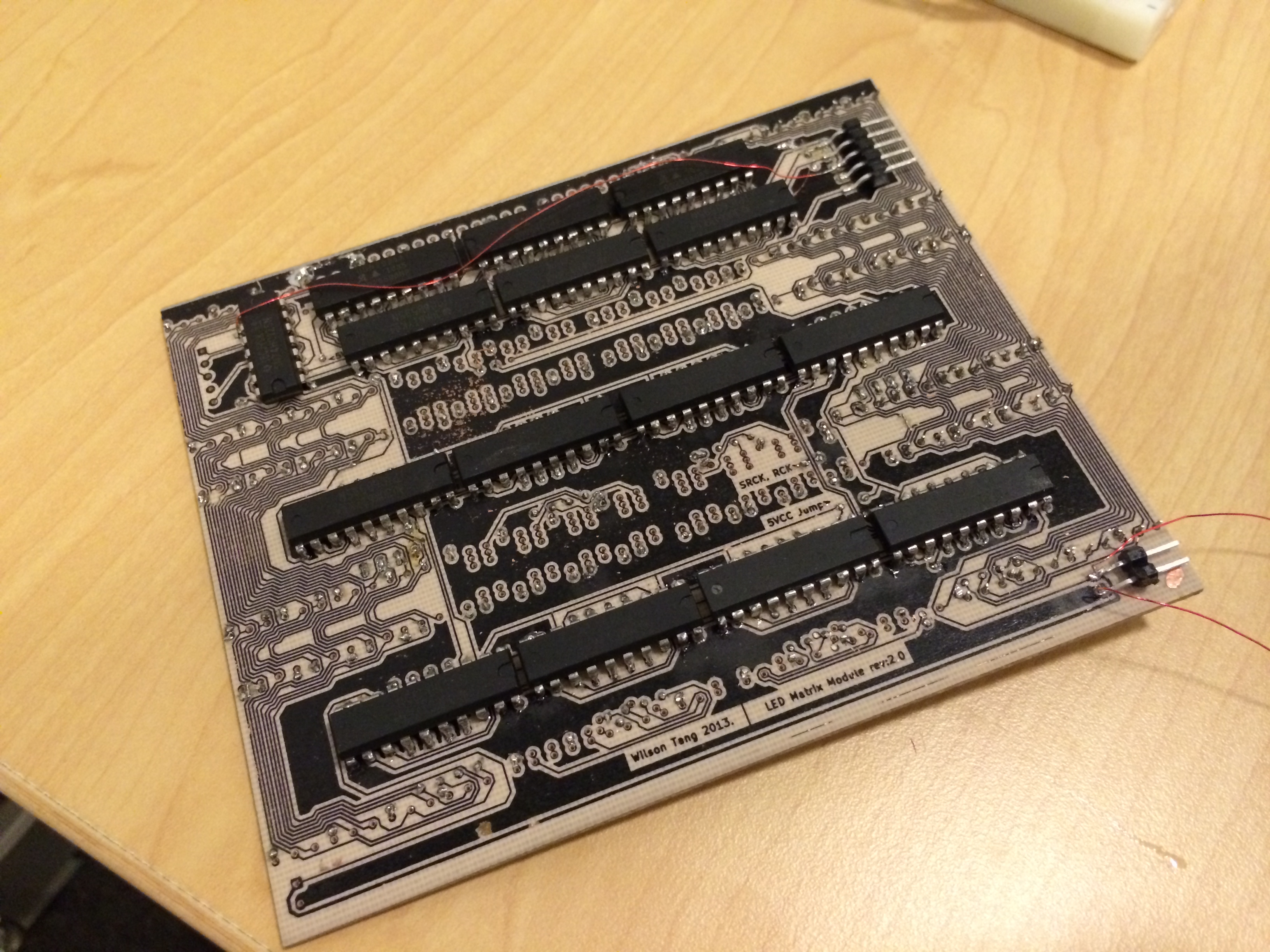
Using the usual toner transfer method to etch PCBs I was able to skip wiring only half of the traces on the board manually. As I decided to use only a single sided board due to my inexperience at etching, I had to manually wire many of the traces on the board. Although tedious, this only took a week versus the four that it took to hand wire the entire thing. An improvement at best.
After the completion of this first hand-etched module, I came to the realization that this was only a slight improvement on the hand wired version in terms of speed and labor. But I felt that I had no choice due to the large cost of PCB manufacturing. At this point I was ready to replace the slow Arduino that had powered the prototypes up until this point with a Raspberry Pi. The Raspberry Pi’s greater speed allowed me to refresh the display at a rate of 60 Hz while spitting out 243 bytes per row. Attaching the display to the Raspberry Pi was as simple as taking the Pi’s SPI output and driving it with wiringPi to the display. Full code is available on my GitHub. I wanted to be able to only have one cable going to the entire display, so I put the Raspberry Pi on a USB Wi-Fi module and powered it via a 5V DC source which also drove the display. Soon after getting everything up and running however, disaster struck. For reasons that I do not recall, I decided to make both the 12V input on the power supply and the 5V input on the display with identical DC barrel jacks. I quickly learned that the Raspberry Pi cannot survive 12V straight into the USB input and neither could any of the shift registers on the display.
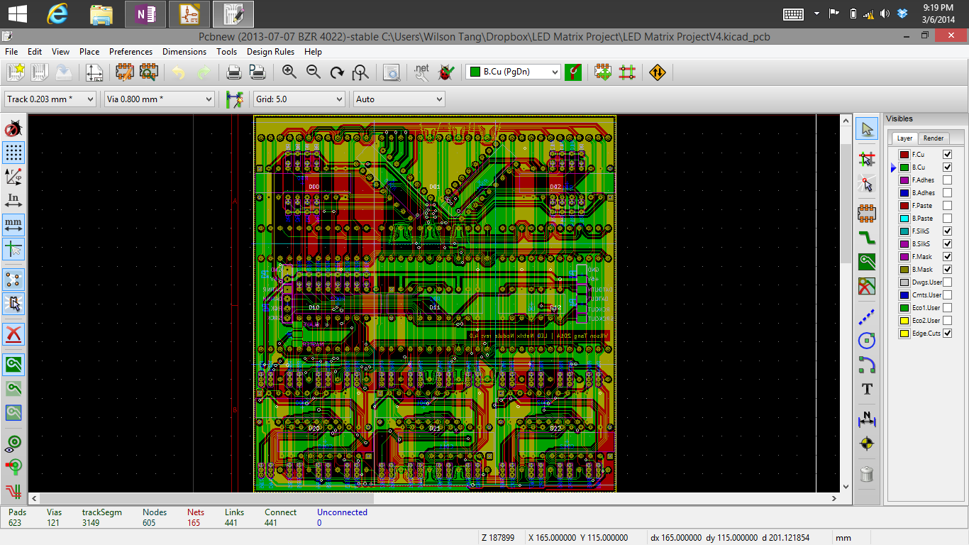
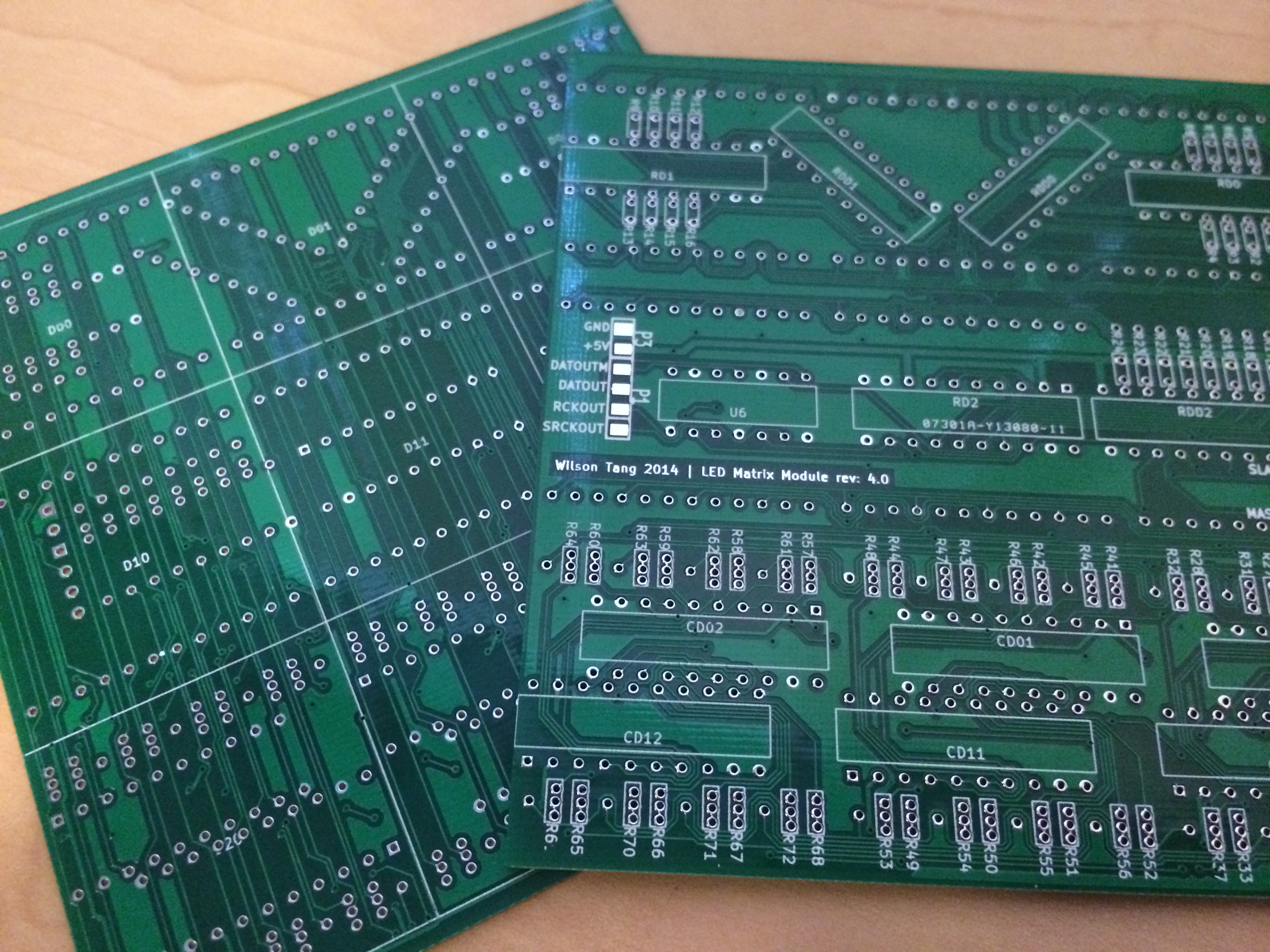
After this point, I knew that I could not feasibly produce another ten displays where I would have to each and wire each board. It just took way too much time. Luckily, after the accident I happened upon a fairly cheap PCB manufacturer that allowed me to finish the display. A quick redesign was in order to suit the manufacturer’s specifications. The final design is shown below.
With these boards I was then able to solder and create ten fully working modules within two weeks.
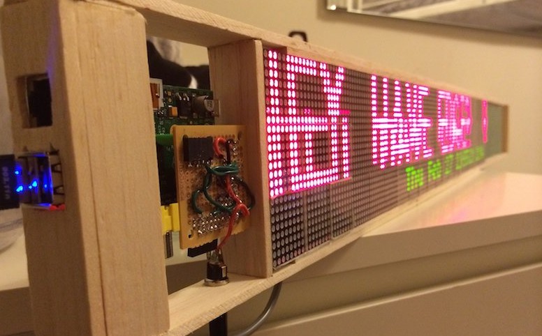
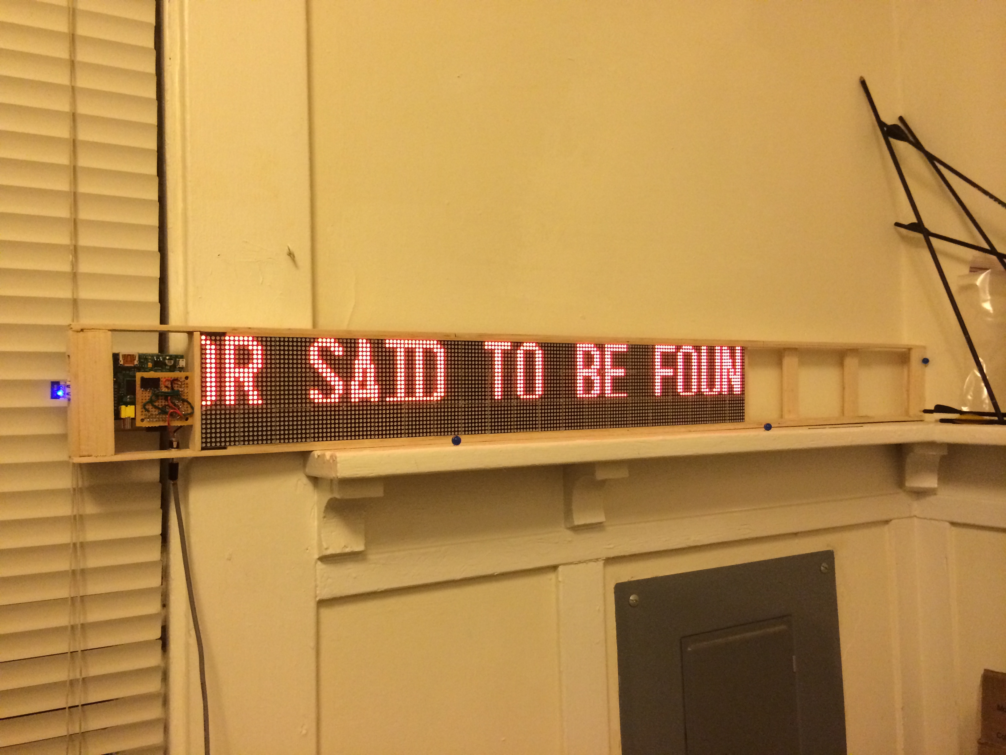
From the start I knew I wanted to mount the display in some kind of wood frame on the wall. Like my PCB design, I went straight into building the frame from some balsa wood. The modules were built such that they slid into tracks on the top and bottom interior of the frame so that I could easily remove them if needed without completely destroying the frame.
The greatest lesson I learned from this project is to avoid large scale hand etching. Hand etching is a great tool for rapid prototyping, but when you get beyond that stage, nothing beats professionally manufactured fully featured boards. In the end, I did spend more than I wanted to, but surprisingly I didn’t spend as much as I would have on a commercial display. I probably would have saved a lot of money if I had thought this through from the beginning, but what fun is that? Schematics and code to display the news are on my GitHub linked above.
Hello. I am currently a third year undergraduate in EECS at the University of California, Berkeley and my hobbies range from target archery to tinker and making whatever I can.
When you buy through links on our site, we may earn an affiliate commission.
Our websites use cookies to improve your browsing experience. Some of these are essential for the basic functionalities of our websites. In addition, we use third-party cookies to help us analyze and understand usage. These will be stored in your browser only with your consent and you have the option to opt-out. Your choice here will be recorded for all Make.co Websites.
Allow Non-Necessary Cookies
Escape to an island of imagination + innovation as Maker Faire Bay Area returns for its 15th iteration!
Buy Tickets today! SAVE 15% and lock-in your preferred date(s).